26
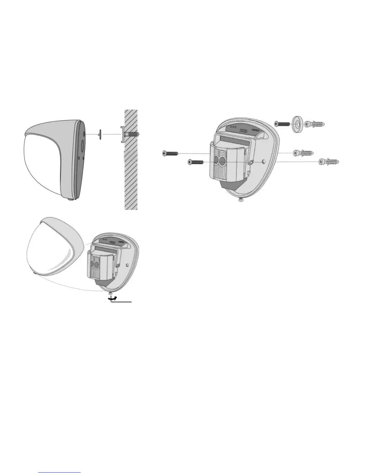
Screw the device to the wall and make sure that the
anti-removal wall contact is positioned correctly and the
switch is closed. [Fig. 4]. For mounting, two spare
clamping feet are provided. One is 1 mm, the other one
is 2 mm away from the original one. This plug
connection can be removed by gently pulling the pin.
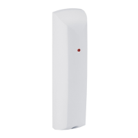
[Fig. 2] When changing the electronic module, always
make sure that the LED is facing forwards to ensure
the sensor is aligned correctly. [See section “Aligning
and masking”]
When the detector is correctly positioned and installed, replace the front cover and lock it
as shown. [Fig. 5]