Analog Disc Input Board
AD-20
Thank you for selecting the Accuphase AD-20 Analog Disc Input Board. This option board is
designed for installation in one of the option slots on the rear of an Accuphase component. It
provides a set of inputs for signals from an analog record player.
Usage details of the board will differ, depending on the Accuphase component in which the
board is installed. To ensure correct use, please read this document first and then refer to the
instruction manual of the Accuphase component for additional information.
●
1
S1: MC LOAD − MC input impedance selector
* In components with two slots, two boards can be installed.
Usage
* The S1 setting affects both the left and right channels.
*Be sure to set both the S2 and S3 switches to the same position.
●
2
S2, S3: FILTER − Subsonic filter on/off
Fig. 1 Fig. 2
Guide rail
Guide rail
7
2
4
-
0
0
1
9
-
0
0
7
2
4
-
0
0
2
0
-
0
0
T
O
S
H
I
B
A
7
4
H
C
T
O
N
F
V
5
1
0
2
0
MHz0.2
4
Sub
panel
Option
board
This filter has a cut-off frequency of 25 Hz and a steep
attenuation slope of -12 dB/octave. lt cuts off unwanted
subsonic signal components without affecting the audible
range.
*The S4 setting affects both the left and right channels.
●
3
S4: MC/MM − Equalizer gain selection
S1:MCLOAD
MC input impedance selector:
10/30/100 ohms
S2,S3:FILTER
Subsonic filter on/off
S4:
MC/MMselection
If the component where the board is installed
has an MC/MM selector on the front panel,
there is no need to set the S4 switch.
●
Generally, the input impedance setting should be
about 2 to 3 times the rated cartridge impedance.
However, since the requirements of some car-
tridges may vary, the final setting should be deter-
mined by ear.
INSTRUCTION MANUAL
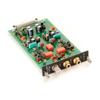
LEFT, RIGHT analog record player input jacks
Connect the output cable from the analog record player
to these jacks.
GND terminal
Connect the ground cable that emerges from the ana-
log record player to this terminal.
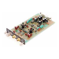
DIP switches S1, S2, S3, S4 Set these switches to the required positions before inserting the board.
Note: Use a sharp pointed object to move the switch levers and make sure that the levers are set fully
to one side. If a lever is set only half-way, correct operation is not possible.
As a general guideline, set this switch as follows :
For MC cartridges with internal impedance of 20
ohms or more : 100 ohm position
For MC cartridges with internal impedance of less
than 20 ohms : 30 ohm or 10 ohm position
ACCUPHASE LABORATORY, INC.
2-14-10, SHIN-ISHIKAWA, AOBAKU, YOKOHAMA 225-8508, JAPAN
J091X 820-3236-10(B3) PrintedinJapan
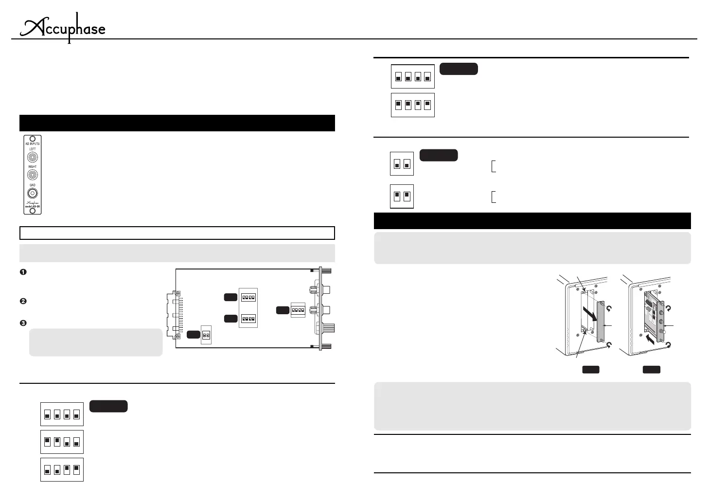
Installation
Set the power switch of the Accuphase compo-
nent to OFF.
On the rear panel, loosen the two screws at the
top and bottom and remove the panel covering
one option slot (see Figure 1).
Insert the option board by sliding it into the top
and bottom guide rails of the slot (see Figure 2).
When the board touches the internal connector,
give it a slight push until the board is firmly seated.
(The board must be flush with the panel.)
Secure the board with the two screws at the top
and bottom.
2
1
3
4
* The illustration shows the E-560.
MM:
Use this position for moving magnet cartridges with high output
Gain: 36dB
Input Impedance : 47 kohms
MC: Use this position for moving coil cartridges with low output
Gain : 62dB
Input Impedance : As selected with S1
Caution
●
Before inserting or removing an option board, be sure to turn the power of the
Accuphase component off to prevent the risk of damage.
●
Tighten the two fastening screws firmly. If the screws are not properly secured,
ground connection will be impaired and damage may occur.
Caution
Do not touch circuit components, solder areas, or exposed parts of connectors,
to prevent possible damage and contact problems. Hold the board only at the
PCB edges or the rear panel.
AD-20 component side (location of switches S1 - S4)
S1
S3
S2
S4
FILTER
MC LOAD
30
10
MC
MM
ON
OFF
ON
OFF
1
ON
234
1
ON
23
4
1
ON
2
1
ON
23
4
Factory default
setting
1,2,3,4:OFF
1,2,3,4:ON
OFF
ON
1
ON
234
1
ON
23
4
Factory default
setting
1,2:OFF
1,2:ON
MM
MC
1
ON
2
1
ON
2
Factory default
setting
1,2,3,4:OFF
3,4:OFF
1,2:ON
3,4:ON
1,2:OFF
100Ω
30Ω
10Ω
1
ON
234
1
ON
23
4
1
ON
23
4
 Loading...