1515
negative pole of the battery is connected to the TN2-6000(S)negative pole of the battery is connected to the TN2-6000(S)
UPS with black wire. The green and yellow ribbon wire isUPS with black wire. The green and yellow ribbon wire is
connected to the ground of the battery cabinet.connected to the ground of the battery cabinet.
3. 3. TTo complete o complete the conthe connection by nection by plugging the plugging the connector of connector of thethe
external battery cable into the external battery socket of the UPS.external battery cable into the external battery socket of the UPS.
Do not attempt to connect any loads to the UPS now. You shouldDo not attempt to connect any loads to the UPS now. You should
connect the input power wire to the right position first. And thenconnect the input power wire to the right position first. And then
set the breaker of the battery pack in the “ON” position. After thatset the breaker of the battery pack in the “ON” position. After that
set the input breaker in the “ON” position. The UPS begins toset the input breaker in the “ON” position. The UPS begins to
charge the battery packs at the time.charge the battery packs at the time.
5.4 Parallel operation5.4 Parallel operation
1. Brief introduction of the redundancy1. Brief introduction of the redundancy
N+X is currently the most reliable power supply structure. NN+X is currently the most reliable power supply structure. N
represents the minimum UPS number that the total load needs; Xrepresents the minimum UPS number that the total load needs; X
represents the redundant UPS number, i.e. the fault UPS number thatrepresents the redundant UPS number, i.e. the fault UPS number that
the system can handle simultaneously. The bigger the X is, the higherthe system can handle simultaneously. The bigger the X is, the higher
reliability of the power system is. For occasions where reliability isreliability of the power system is. For occasions where reliability is
highly depended on, N+X is the optimal mode.highly depended on, N+X is the optimal mode.
As long as the UPS is equipped with parallel cables, up to 3 UPSs canAs long as the UPS is equipped with parallel cables, up to 3 UPSs can
be connected in parallel to realize output power sharing and powerbe connected in parallel to realize output power sharing and power
redundancy.redundancy.
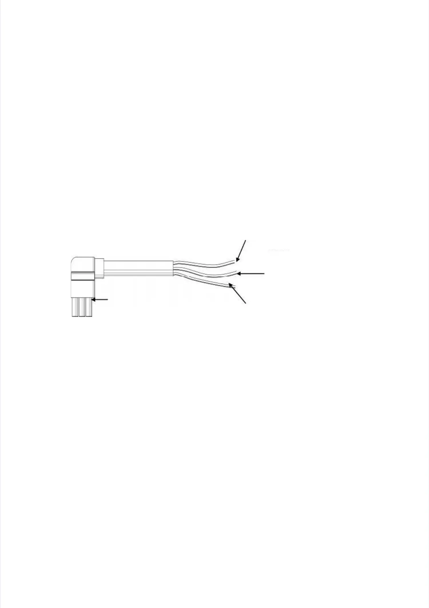
The blue & brown or red wires for connection to theThe blue & brown or red wires for connection to the
positive terminal of the battery pack outputpositive terminal of the battery pack output
The black & white or blackThe black & white or black
wires for connection to thewires for connection to the
negative terminal of thenegative terminal of the
battery pack outputbattery pack output
The green and yellow ribbon wireThe green and yellow ribbon wire
for connection to the ground offor connection to the ground of
the battery cabinetthe battery cabinet
The receptacle forThe receptacle for
connecting the UPSconnecting the UPS
 Loading...