ACE124
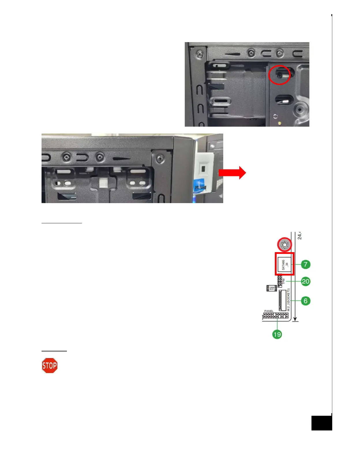
Step 6: Remove 1 Phillips screw on the opposite
side of the case.
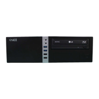
Step 7: Pull out the DVD drive.
Reinstallation:
Step 8: To reinstall the Optical Drive, follow the uninstallation steps
backwards.
Step 9: Slide optical drive into the front drive bay in the desired location.
Step 10: Insert (2) screws on the left side of the chassis (when looking from
the front) and (1) screw on the right side of the chassis (when looking from
the front).
Step 11: Reconnect SATA power header to optical drive from PSU and SATA
data cable from optical drive to motherboard. The suggested header for the
optical drive is SATA6G_3.
Disposal:
Selective Treatment/ Special Handling Per Annex VII, Directive 2012/19/EU: The optical
drive contains a printed circuit board of greater than 10 sq. cm and must be removed
from the device and must be disposed of, or recovered, in compliance with the requirements of
Directive 2008/98/EC.