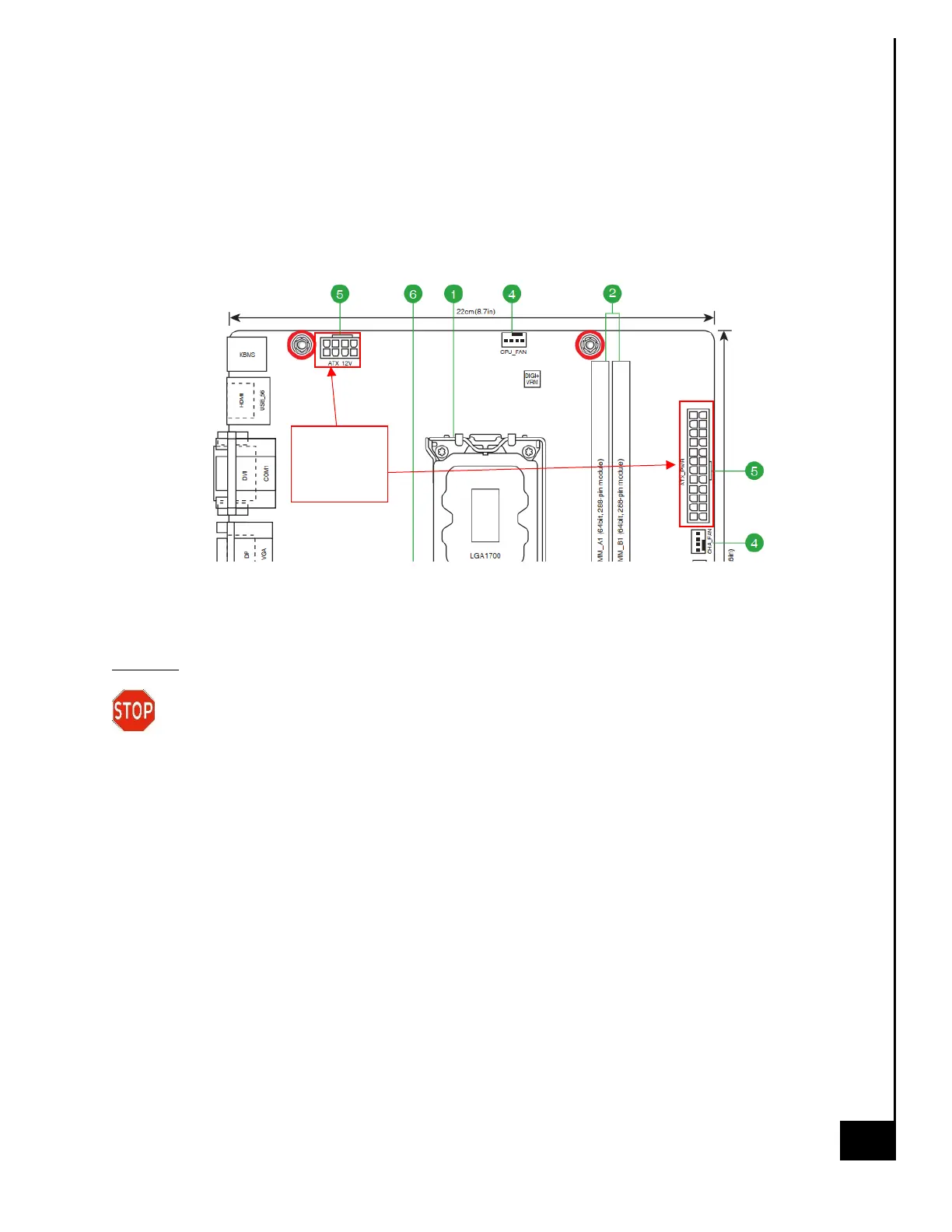
Step 9: Reconnect the required power cables. Depending on the configuration of system this
may vary, but the basic system required connection of the following:
• 24 Pin ATX_PWR (see motherboard diagram below for location)
• 8 Pin ATX_12V (see motherboard diagram below for location)
• SATA Power to HDD
• SATA Power to Optical Drive
Motherboard Diagram for PSU Connections
Disposal:
Selective Treatment/ Special Handling Per Annex VII, Directive 2012/19/EU: The PSU
contains a printed circuit board of greater than 10 sq. cm and must be removed from the
device and must be disposed of, or recovered, in compliance with the requirements of Directive
2008/98/EC.
 Loading...