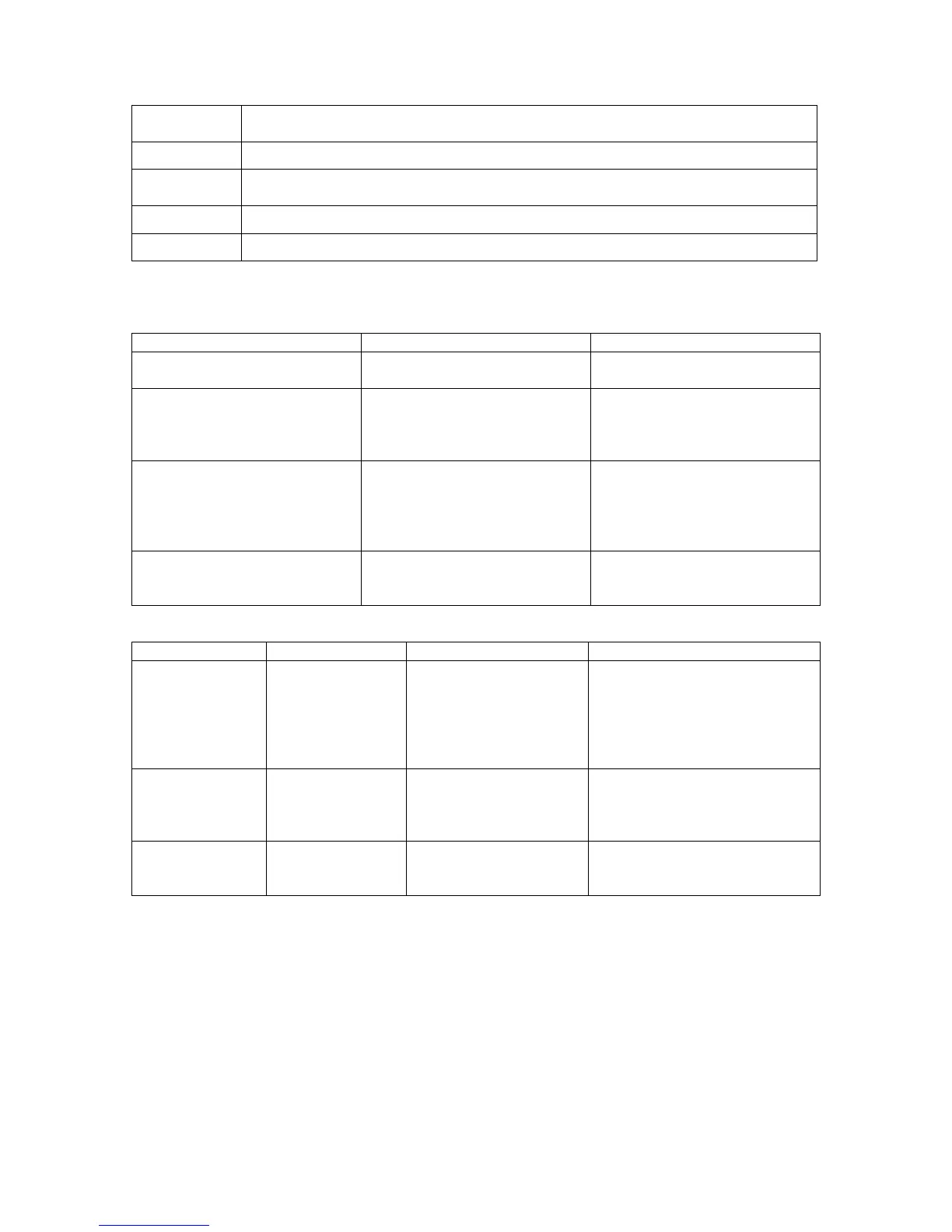
Lock
Setting
Description
1 Locks up all Setup Mode parameters.
2 Locks up all Setup Mode parameters and all Operation Mode parameters except
the initial screen of Operation Mode. Only setpoint parameter can be adjusted.
3 Locks up all the parameters.
oFF No lock, any data can be changed.
Table 3 – Key Lock Level Descriptions
PID Modulation Controller Troubleshooting
Problem Cause Remedy
Error code is displayed. Refer to Error Codes, Causes
and Remedies
Refer to Error Codes, Causes
and Remedies
Displayed PV value seems to
be incorrect
Set measuring range code is
different from that of input
sensor/input signal.
Check if set measuring range
code is correct for input signal.
Correct wiring to input
terminals of sensor.
Display on the front panel
goes out and the instrument
does not operate
Problem with power supply
and wiring connection.
Deterioration of the product.
Inspect portions related to
power source and wire
connection.
Examine the product and
repair or replace.
Key unable to be operated Key lock is in effect.
Deterioration of the product.
Release Key lock.
Examine the product and
repair or replace.
Error Codes, Causes and Remedies
Screen display Problem Cause Remedy
HHHH
Higher limit scale
over.
A break in RTD wiring.
Input measured value
exceeded measuring
range by 10%.
Check RTD. Input A wiring for
a possible break. If wiring has
no problem, replace RTD.
Check if set code of measuring
range is correct for input
signal.
LLLL
Lower limit scale
over
Input measured value
lower than measuring
range by 10%.
Check wiring of reverse
polarity for measured value
input or wiring for a possible
break.
b - - -
Break of RTD
input wiring
A break of B.
Break of ABB
Check RTD input terminals A,
B and B for breaks. If wiring
has no problem, replace RTD.
 Loading...