Page 3
MODEL NUMBER IDENTIFICATION
GETTING STARTED
1. Install the control as described on page 4.
2. Wire your control following the instructions on page 6. Please read
the Precautions section located at the end of this manual before wiring
the control.
3. For best results when programming changes are necessary, make all
changes to the Initial Setting mode (Pages 13-14) before making
changes to the Regulation Mode (Pages 11-12) or Operation Mode
(Pages 10). If any error messages occur, check the Diagnostic Error
Message Section (Page 18) for assistance.
16C
OUTPUT 1
2 = Voltage Pulse
3 = Relay
5 = Current
6 = Linear Voltage
8C
OUTPUT 1
2 = Voltage Pulse
3 = Relay
5 = Current
6 = Linear Voltage
4C
OUTPUT 1
2 = Voltage Pulse
3 = Relay
5 = Current
6 = Linear Voltage
INSTALLATION
Mount the instrument in a location that will not be subject to excessive
temperature, shock, or vibration. All models are designed for mounting in an
enclosed panel.
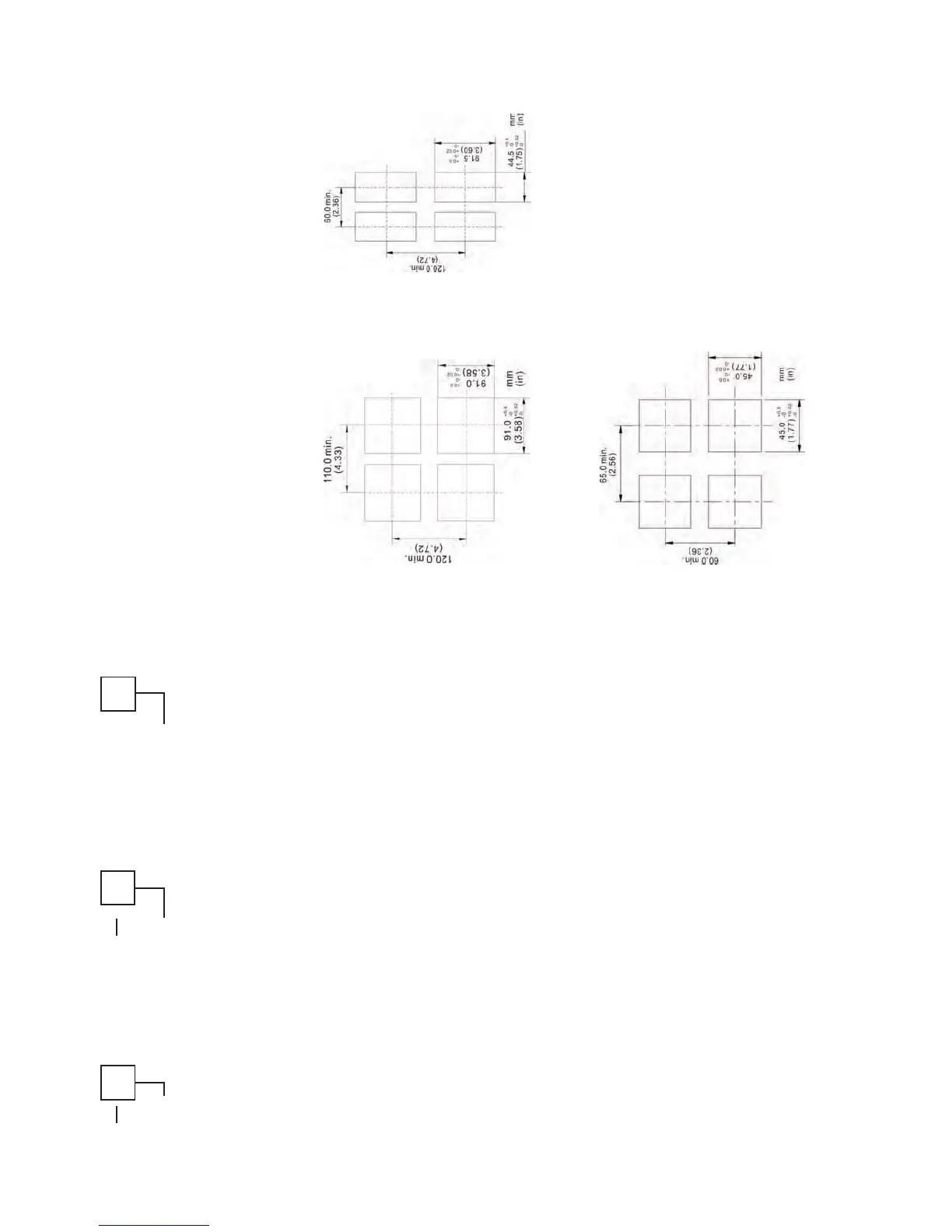
Select the position desired for the instrument on the panel. Prepare the
panel by cutting and deburring the required opening per the panel cut out
dimensions listed below. Follow the mounting instructions listed on page 5.
Lastly, wire the controller per the appropriate wiring diagram listed on page
6.
PANEL CUTOUT DIMENSIONS
Page 4
4C 8C
16C
 Loading...