50 Hanover Road, Florham Park, New Jersey 07932 www.ascovalve.com
Page 4 of 4 Form No.V6584R8
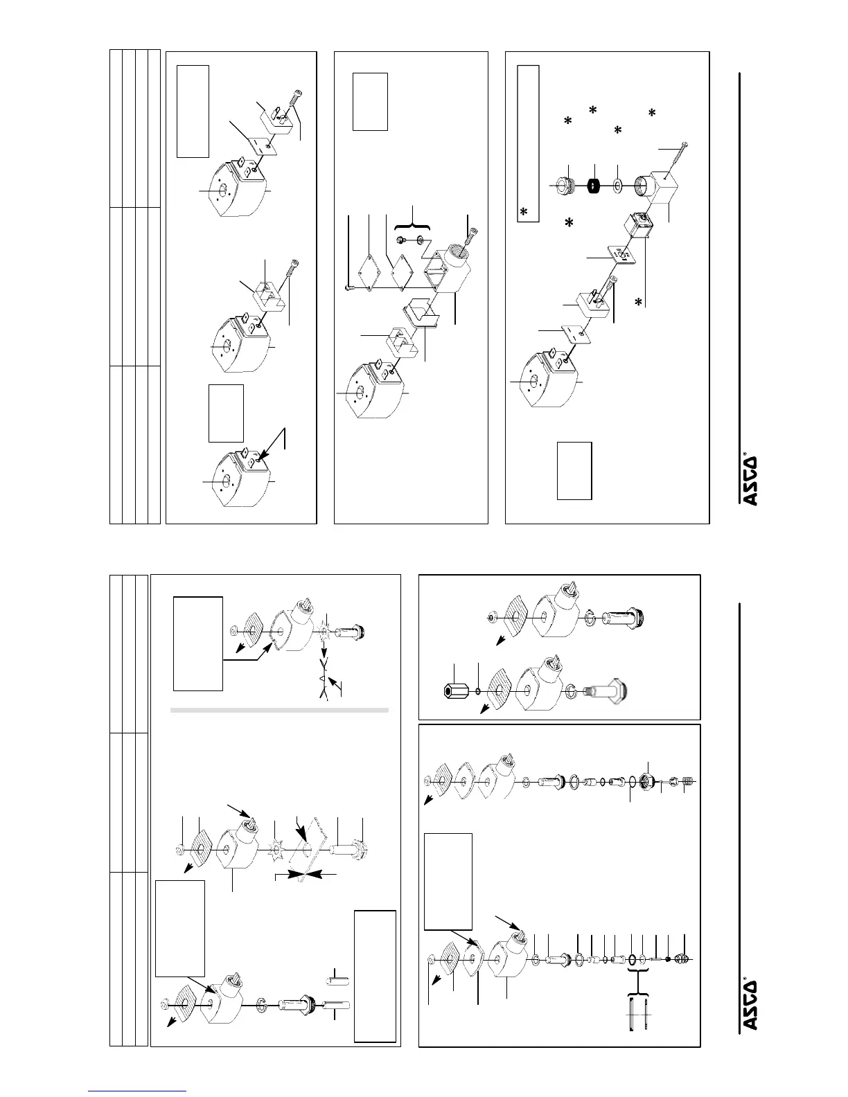
Torque Chart
Part Name Torque Value in Inch-Pounds Torque Value in Newton-Meters
terminal block screws 10 ± 2 1,1 ± 0,2
socket head screw 15 - 20 1,7 - 2,3
center screw 5 ± 1 0,6 ± 0,1
screw terminal
adapter
gasket
DIN terminal
adapter
socket head screw
socket head
grounding screw
Open-Frame Solenoid
Open-Frame Solenoid Open-Frame Solenoid
with Screw Terminals.
Socket head screw is
used for grounding.
with DIN Terminals
tapped hole for
#10-32 grounding screw
(not included)
See
torque chart
above
terminal
block
screw
with 1/4 Spade Terminals
(5/32 hex key wrench)
(5/32 hex key wrench)
Indicates parts supplied
in Termination Module
Kit No. K256104
Figure 4. Open-frame solenoids
cover screw
cover gasket
cover
junction box gasket
junction box with
and grounding terminal
socket head screw
screw terminal block
(see note)
grounding screw
and cup washer
Junction Box Solenoid
Note:
Junction box with screw terminals
shown. With screw terminal
block removed, remaining parts
comprise the junction box for
spade terminal construction.
See
torque chart
above
or Screw Terminals
(5/32 hex key wrench)
1/2 conduit connection
with 1/4 Spade Terminals
Figure 5. Junction box (optional feature)
gland nut
gland gasket
washer
socket head screw
gasket
DIN terminal
connector
connector cover
center screw
adapter
gasket
(see note 1)
DIN connector
terminal block
(see note 2)
Indicates that these parts are included
Open-Frame Solenoid
with DIN Terminal
Notes:
1. Connector cover may be
position shown for alternate
position of cable entry.
2. Refer to markings on DIN
connector for proper
electrical connections.
in DIN plug connector Kit No. K236034
See
torque chart
above
Plug Conector
(5/32 hex key wrench)
rotated in 90 increments from
Figure 6. DIN plug connector kit No. K236034 (optional feature)
50 Hanover Road, Florham Park, New Jersey 07932 www.ascovalve.com
Page 3 of 4Form No.V6584R8
Torque Chart
Part Name Torque Value Inch-Pounds Torque Value Newton-Meters
solenoid base sub-assembly & adapter 175 ± 25 19,8 ± 2,8
pipe adapter 90 maximum 10,2 maximum
nameplate/
core
(AC) (DC)
solenoid base
sub-assembly
0.9375-26 UNS -2A
thread
core
red cap
finger
Tapped hole in core
0.250-28 UNF-2B
retainer
.062 to .093 maximum
thickness of panel
for mounting
0.69 diameter
mounting hole
push solenoid down.
Then pry here to lift
nameplate/retainer
Alternate
Construction
Panel Mount
0.38 minimum full thread (DC)
0.63 minimum full thread (AC)
Remove red cap and
push solenoid down.
Then pry here to lift
nameplate/retainer
Remove red cap and
and push to remove.
and push to remove.
washer
finger washer
solenoid
with 1/2 NPT
grounding wire -
green or green with
yellow stripes
collar to face
valve body
Side View
Figure 1. Series 8003G solenoids
pipe adapter
plugnut gasket
plugnut assembly
solenoid base gasket
core(small end up)
retainer gasket
retainer
stem
disc
disc spring
bonnet washer
cutaway view to
show positioning
of retainer in
gasket recess
disc holder
adapter
adapter
gasket
disc holder
assembly
spring
solenoid base
sub-assembly
nameplate/
retainer
red cap
Air Only Construction
Vent to Atmosphere
With
spacer
push solenoid down.
Then pry here to lift
nameplate/retainer
Remove red cap and
Adapter
Without
Adapter
and push to remove.
spring washer
grounding wire -
green or green with
yellow stripes
solenoid
with 1/2 NPT
Figure 2. Series 8202G solenoids Figure 3. 3-Way Construction
 Loading...