20
Switch
and
LED
Indicators
Introduction
This section discusses the different LED indicators located on the :
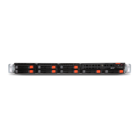
Front panel
Hot-plug HDD carrier
LAN port
Knowing what each LED indicator signifies can aid in problem diagnosis and troubleshooting.
Front Panel
LED
Description
Numbe
Status Description
1 Power Green Solid On System is powered on.
2 System ID Blue Solid On System identification is active
-- Off System identification is disabled
3 HDD Activity Green Blink HDD access
-- Off No HDD access
4 System Status Green Solid on Running or normal operation
Solid on Critical or non-recoverable condition
(Power module or voltage power supply
failure or critical temperature)
Blink Non-critical condition
-- Off System not ready
May indicate the following:
POST error
NMI event
Processor or terminator missing
5 LAN1 Activity Green Solid on Link between system and network or no
access
Green Blink Network access
-- Off Disconnect/Idle
6 LAN2 Activity Green Solid on Link between system and network or no
access
Green Blink Network access
-- Off Disconnect/Idle

 Loading...