Do you have a question about the Acer TravelMate P243-M and is the answer not in the manual?
Summary of the computer's hardware features, including OS, CPU, Chipset, Memory, Display, Graphics, Audio, Storage, Webcam, Wireless, Security, Power, Input/Output ports, and Software.
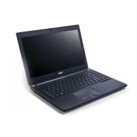
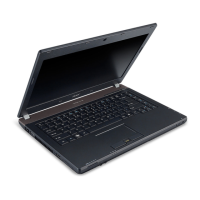
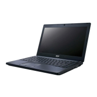
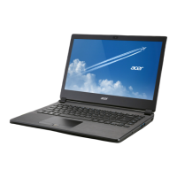
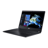
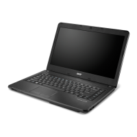
Visual guide to the notebook's external components and their functions, including opened and closed views.
Explanation of touchpad functionality, including cursor movement, button operations, and gesture controls.
Details on keyboard layout, lock keys (Caps Lock, Num Lock, Scroll Lock), and embedded numeric keypad functionality.
Description of Windows-specific function keys like the Windows Logo key and Application key.
Explanation of keyboard hotkeys for accessing computer controls like screen brightness and volume.
A graphical representation of the system's internal components and their interconnections.
Detailed tables outlining computer specifications, including dimensions, weight, power, temperature, humidity, altitude, shock, and vibration.
Information on the key integrated circuits and chipsets present on the system board.
Detailed specifications for various CPU models, including speed, cores, cache, package, and voltage.
Details on system memory specifications, including controller, size, sockets, speed, voltage, and package type.
Information on the video interface, including chipset, package, compatibility resolutions, and sampling rate.
Details regarding the BIOS vendor, version, ROM type, size, and features.
Specifications for the keyboard, including type, number of keypads, Windows logo key, and simultaneous internal/external keyboard support.
Specifications for various hard disk drive models, including vendor, capacity, speed, buffer size, and transfer rates.
Specifications for BD/DVD Super Multi drives, including vendor, performance, buffer memory, interface, and applicable disc formats.
Detailed specifications for the 14.0-inch LCD panel, including resolution, brightness, contrast ratio, and viewing angles.
Information on the Unified Memory Architecture (UMA) graphics controller, including VGA chip and features.
Information on the discrete graphics controller, including VGA chip, features, and supported resolutions.
Details about the LAN interface, including chipset, connector type, location, and features.
Specifications for the Bluetooth module, including chipset, interface, and supported features.
Details on the audio codec and amplifier hardware, including features and capabilities.
Specifications for USB ports, including compliance level, number of ports, location, and output current.
Specifications for the HDMI port, including compliance level, data throughput, number of ports, and location.
Details on the battery, including vendor, model, type, capacity, number of cells, and package configuration.
Specifications for the AC adapter, including vendor, input rating, maximum input current, inrush current, and efficiency.
Information on system power management states (Mech. Off, Soft Off, Working, Suspend to RAM, Save to Disk).
Explanation of system LED indicators for lock status, system state, HDD access, communication, power button, and battery status.
Table detailing system interrupt (IRQ) assignments and their corresponding system functions.
A map of I/O addresses and their system functions in the shipping configuration.
Guide to the BIOS Setup Utility, a hardware configuration program for system settings.
Instructions on navigating the BIOS utility menus, items, and changing parameter values.
Details on the BIOS Information tab, summarizing computer hardware information.
Explanation of the BIOS Main tab parameters for setting system time, date, boot options, and recovery.
Information on the BIOS Security tab, covering parameters for safeguarding the computer from unauthorized use.
Details on the BIOS Boot tab, allowing changes to the order of boot devices.
Description of the BIOS Exit tab for saving or discarding changes and quitting the utility.
Procedures for updating BIOS flash memory for new program versions, features, or corruption recovery.
Step-by-step guide for using the DOS Flash Utility to update the BIOS.
Instructions for using the WinFlash Utility to update the BIOS from within Windows.
Procedure for clearing Insyde HDD/BIOS passwords, including warnings and error status.
Detailed steps for removing Insyde BIOS passwords using a software utility.
Procedure for clearing BIOS passwords specifically related to the HDD.
Information on various system utility tools, including DMITools, UUIDTools, LAN MAC EEPROM, and Crisis Disk Recovery.
Guide on using the DMI Tool to copy BIOS information to EEPROM for hardware management.
Instructions for using the UUID Tool to copy BIOS information to EEPROM for hardware management.
Steps to write MAC (Media Access Control) information to EEPROM using the LAN.BAT utility.
Procedure for performing BIOS recovery using a crisis USB disk.
Overview of the chapter's content, including maintenance, tools, and component removal/installation procedures.
List of recommended tools and equipment for performing maintenance procedures.
Steps to perform before starting any maintenance procedures, including removing power and cables.
Overview of the disassembly process, divided into external, main unit, and LCD module disassembly sections.
Steps and flowchart for disassembling external components like ODD, Keyboard, and HDD.
Procedure for removing the dummy card from the system.
Detailed steps for removing the battery pack from the computer.
Procedure for removing the Optical Disk Drive module, including bezel and bracket.
Step-by-step guide for removing the keyboard, including disconnecting FPC and releasing latches.
Procedure for removing the base door to access internal components.
Steps for removing the WLAN module, including disconnecting antennas and securing screws.
Procedure for removing DIMM modules by releasing clips and disconnecting from the mainboard.
Steps for removing the HDD module, including disconnecting cables and bracket.
Flowchart and steps for disassembling the main internal components of the computer.
Procedure for removing the upper case, including disconnecting touchpad FPC and screws.
Steps for removing the IO board, including disconnecting FPC and securing screws.
Detailed steps for removing the mainboard, including disconnecting cables and screws.
Procedure for removing the speaker modules, including speaker cables and mounting screws.
Steps for removing the RTC battery, including disconnecting cable and prying from adhesive.
Procedure for removing the thermal module, including disconnecting fan cable and captive screws.
Steps for removing the CPU processor, including rotating the cam lock and lifting the processor.
Procedure for removing the LCD module, including antennas, screws, and cable management.
Steps for removing the support brackets securing the LCD panel.
Procedure for removing the DC-in jack module from the base assembly.
Flowchart and screw list for disassembling the LCD module components.
Steps for removing the LCD bezel, including releasing latches and screws.
Procedure for removing the camera module, including disconnecting cable and adhesive.
Steps for removing the LCD panel from the LCD cover, including microphone and screws.
Procedure for removing the LCD bracket from the LCD panel.
Steps for removing the LVDS and camera cables from the LCD panel.
Steps for reassembling the LCD module, focusing on LVDS and camera cables.
Procedure for installing and securing the LCD bracket to the LCD panel.
Steps for installing the LCD panel onto the LCD cover and securing it with screws.
Procedure for installing the camera module and connecting its cable.
Steps for attaching and securing the LCD bezel to the LCD module.
Steps for reassembling the main internal components of the computer.
Procedure for installing the DC-in jack module and securing its cable.
Steps for installing and securing the support brackets.
Procedure for installing the LCD module, aligning hinges, and securing with screws.
Steps for installing the CPU processor, including placing it on the mainboard and tightening the cam lock.
Procedure for replacing the thermal module, including applying thermal grease and securing screws.
Steps for installing the RTC battery, including securing it with adhesives and connecting the cable.
Procedure for installing speaker modules, securing screws, and routing speaker cables.
Steps for installing the mainboard, including connecting various cables and securing screws.
Procedure for installing the IO board, connecting FPC, and securing with screws.
Steps for installing the upper case, including connecting FPC and securing screws.
Steps for reassembling external modules like HDD, DIMM, and WLAN.
Procedure for installing the HDD module, including brackets, cables, and connectors.
Steps for installing DIMM modules into the mainboard connectors and locking clips.
Procedure for installing the WLAN module, connecting antennas, and securing with screws.
Steps for installing and securing the base door.
Procedure for installing the keyboard, connecting FPC, and securing latches.
Steps for installing the ODD module, including bezel, bracket, and securing screws.
Procedure for installing the battery pack into the battery bay.
Steps for inserting the dummy card until the spring latch locks.
Overview of troubleshooting procedures and general information for identifying and resolving computer problems.
Troubleshooting steps for systems that do not power on or shut down intermittently.
Procedure for troubleshooting when the display does not work or POST/video does not appear.
Troubleshooting steps for LCD failures, including checking modules, connectors, and cables.
Troubleshooting steps for internal keyboard failures, checking FPC connection and keyboard functionality.
Troubleshooting steps for touchpad failures, checking mainboard connection and touchpad board.
Troubleshooting steps for internal speaker failures, checking M/B SPK cable and logic components.
Troubleshooting steps for internal microphone failures, checking MIC cable and module functionality.
Troubleshooting steps for USB port failures, checking USB/B to M/B cable and USB/B components.
Troubleshooting steps for failures related to other system functions, drives, or external modules.
Guidance for diagnosing intermittent system hang problems caused by various factors.
Procedures to isolate failing FRUs when diagnostic problems do not identify the specific failed component.
Tables detailing InsydeH2O Functionality POST code ranges and specific phase code descriptions.
Diagrams and descriptions of jumper and connector locations on the mainboard's top and bottom sides.
Procedures for clearing BIOS passwords and performing BIOS recovery using a crisis disk or hot key.
Steps to clear BIOS passwords (Supervisor and User) by using the ClearPwd.EXE utility.
Instructions for performing BIOS recovery from USB storage using a crisis disk.
System exploded diagrams illustrating the placement of major components with corresponding Acer Part Numbers.
Comprehensive list of Field Replaceable Units (FRUs) with categories, descriptions, and Acer Part Numbers.
List of screws used in the system, detailing their size, quantity, and Acer Part Numbers.
Definition and configuration details specific to the TravelMate P243 Series models.
Table detailing Region Option (RO), description, and Acer Part Numbers for various configurations.
Table mapping models to their corresponding CPU and LCD panel specifications.
Table specifying the VGA Chip and VRAM configurations for different models.
Table detailing memory configurations (1 and 2) and HDD 1 specifications for various models.
Table specifying ODD, Extra SW1, and Card Reader configurations for different models.
Table detailing Wireless LAN, Bluetooth, and NB Chipset configurations for various models.
Table specifying Battery, Adapter, and Camera configurations for different models.
List of components tested and verified for compatibility with Windows 7 environment.
Description of online technical support services, resources, and information available for Acer Systems.
| Display Size | 14 inches |
|---|---|
| Display Resolution | 1366 x 768 pixels |
| Weight | 2.1 kg (4.63 lbs) |
| Wireless | Wi-Fi 802.11 a/b/g/n, Bluetooth 4.0 |
| Processor | Intel Core i3/i5/i7 (depending on configuration) |
| Storage | 500GB HDD |
| Graphics | Intel HD Graphics 4000 |
| Operating System | Windows 7 Professional |
| Battery | 6-cell Li-ion battery |
| Ports | USB 3.0, USB 2.0, HDMI, VGA, Ethernet |