Introduction
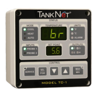
This manual provides information about how to properly install a TankNET TC-1
controller with power line communications. Specifically, it covers:
· General precautions and installation guidelines
· Basic controller dimensions
· Mounting brackets installation
· Mounting of controller onto ice shield of tank
· Controller Inlet connections
· Electrical wiring including: line voltage, cool/heat outputs, 2-wire or 4-wire
TankNET temperature probe input, analog outputs (proportional control) and
optional pump control outputs
· Internal ribbon cable connections (power and communications)
· Final assembly of controller display to power supply
Safety Information
We use note, caution and warning symbols throughout this manual to draw your
attention to important installation, operational and safety information.
A “NOTE” marks a short message to alert you to an important detail
A “CAUTION” safety alert appears with information that is important for protecting your
equipment and performance. Be especially careful to read and follow all cautions that
apply to your application.
A “WARNING” safety alert appears with information that is important to protecting you,
others and equipment from damage. Pay very close attention to all warnings that apply
to your application.
The safety alert symbol (an exclamation point in a triangle) precedes a general warning
or caution statement.
An electrical hazard symbol (an lightening bolt in a triangle) precedes an electrical
shock hazard caution or warning.
CAUTION or WARNING
ELECTRICAL SHOCK HAZARD
CAUTION or WARNING
TC-1 for Power Line Networking Quick Start Installation Guide
Acrolon Technologies, Inc.
 Loading...