Page 1 of 4 AR-B1479 Manual
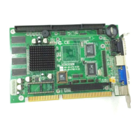
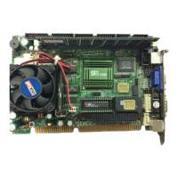
AR-B1479 Manual
Version 1.2
1. SETTING UP THE SYSTEM
1.1 PACKING LIST
! The quick setup manual
! 1 AR-B1479 CPU board
! 1 Hard disk drive adapter cable for 3.5” HDD
! 1 Hard disk drive adapter cable for 2.5” HDD.
! 1 Floppy disk drive adapter cable
! 1 Parallel port adapter cable & 1 RS-232C interface
cable mounted on one bracket
! 1 PS/2 Y-type cable
!
1 Software utility CD
1.2 PC/104 CONNECTOR
(1) 64 Pin PC/104 Connector Bus A & B (PC1)
2 64
1 63
60 Pin PC/104 Connector
(2) 40 Pin PC/104 Connector Bus C & D (PC1)
1
2
39
40
40 Pin PC/104 Connector
1.3 FDD PORT CONNECTOR (CN4)
2
1
1.4 PARALLEL PORT CONNECTOR
(CN3)
Parallel Port Connector
2 26
1 25
13 1
25 14
D-Type Connector
1.5 ETHERNET RJ-45
CONNECTOR (LAN1)
18
1.6 PS/2 MOUSE CONNECTOR
(CN2&PS1)
KBCLK
VCC
KBDAT
MSDAT
6
5
4
CN2
6 Pin Mini-DIN
PS1
2 MSDAT
1 KBDAT
3 GND
4 VCC
6 MSCLK
5 KBCLK
1.7 PS-ON HEADER (CN1)
3 5VSB
2 VCC
1 PS-ON
CN1
1.8 RESET HEADER (J1)
Shorting these two pins will reset the system.
2 1
J1
1.9 POWER CONNECTOR (PWR1)
The PWR1 is a 4-pin power connector. It’s the standard
connectors on all Acrosser boards.
4 +5V
3 GND
2 GND
1 +12V
PWR1
CAUTION:
1.The detail description manual file was attached in
the software utility CD.
2. The bug of STPc CPU causes the AR-B1479
can’t support the floppy only in Win95. But STPc
will try to solve this problem, and we decided to
ado
.
PIN (LAN1) FUNCTION
1 TPTX+
2 TPTX-
3 TPRX+
4 Not Used
5 Not Used
6 TPRX-
7 Not Used
8 Not Used
* When AT power supplier is
applied, jumper 2&3 should
be tied together.(Factory
preset)
* When ATX power supplier is
applied, pin1&pin 3 should
be connect to proper