12
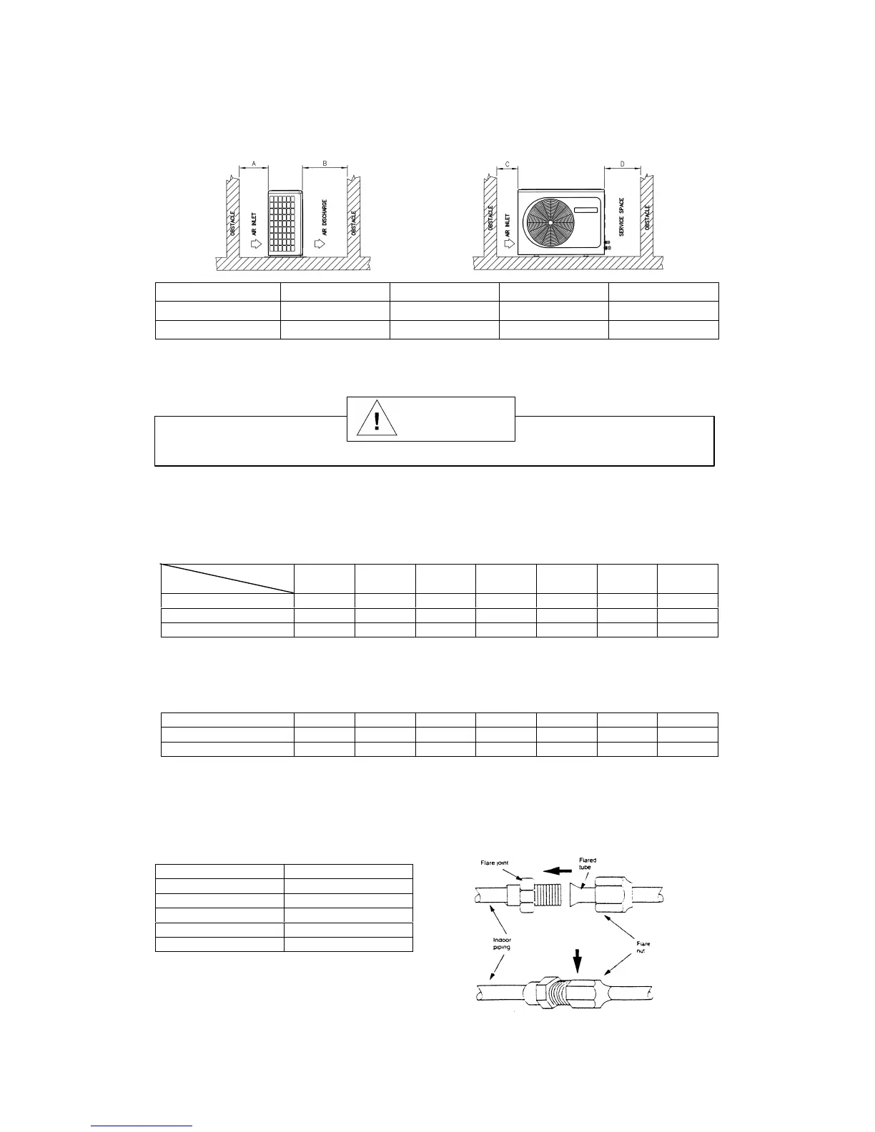
INSTALLATION CLEARANCE
• Outdoor units must be installed such that there is no short circuit of the hot discharge air or
obstruction to smooth air flow. Select the coolest possible place where intake air should not be hotter
than the outside temperature (max. 45°C)
Minimum Distance A B C D
Series I 150 mm 1,000 mm 150 mm 500 mm
Series II 300 mm 1,000 mm 300 mm 500 mm
(3) REFRIGERANT PIPING
Must install a molecular-sieve type filter dryer along the liquid line.
MAXIMUM PIPE LENGTH AND MAXIMUM NUMBER OF BENDS
• When the pipe length becomes too long, both the capacity and reliability drop. As the number of
bends increases, system piping resistance to the refrigerant flow increases. This will lower the
cooling capacity and as a result, the compressor may become defective. Always choose the shortest
path and follow the recommendation as tabulated below :
MODELS
DATA
10 15 20 25 30 40 50
Max. Length (m) 7 10 15 15 20 20 20
Max. Elevation (m) 5 5 8 8 10 10 10
Max. No of Bends 10 10 10 10 10 10 10
PIPING SIZES (FLARE CONNECTION TYPE)
• Piping sizes are as follows :
MODELS
10 15 20 25 30 40 50
Liquid (mm/in)
6.35 (1/4) 6.35 (1/4) 6.35 (1/4) 9.52 (3/8) 9.52 (3/8) 9.52 (3/8) 9.52 (3/8)
Suction (mm/in)
9.52 (3/8) 12.70 (1/2) 15.88 (5/8) 15.88 (5/8) 15.88 (5/8) 19.05 (3/4) 19.05 (3/4)
PIPING CONNECTION TO THE UNITS
• Align the centre of the piping and sufficiently tighten the flare nut with fingers.
• Finally, tighten the flare nut with torque wrench until the wrench clicks.
• When tightening the flare nut with torque wrench, ensure the direction for tightening follows the
arrow on the wrench.
PIPE SIZE (mm/in) TORQUE (Nm)
6.35 (1/4) 18
9.52 (3/8) 42
12.70 (1/2) 55
15.88 (5/8) 65
19.05 (3/4) 78
Caution