22
AWM-G-2009 Application Information
Drilling Holes and Mounting Installation Installation Plate
Caution
Please check the unit weight for each model. Always ensure that the wall is suffi ciently strong to withstandthe weight. If
not, it is necessary to reinforce the wall with plate, beams or pillars.
The unit cannot be directly fi xed onto the wall or the likes. In all cases, the installation plate provided MUSTbe used.
•
•
Paste the installation plan provided on the desired location on the wall and mark the holes location
accordingly.
Ensure that the minimum maintenance and servicing space at the top, left and right side of the unit
isreserved.·Ensure also the levelness of the installation plate.
Drill the screw mounting holes (minimum 4 screws are required).
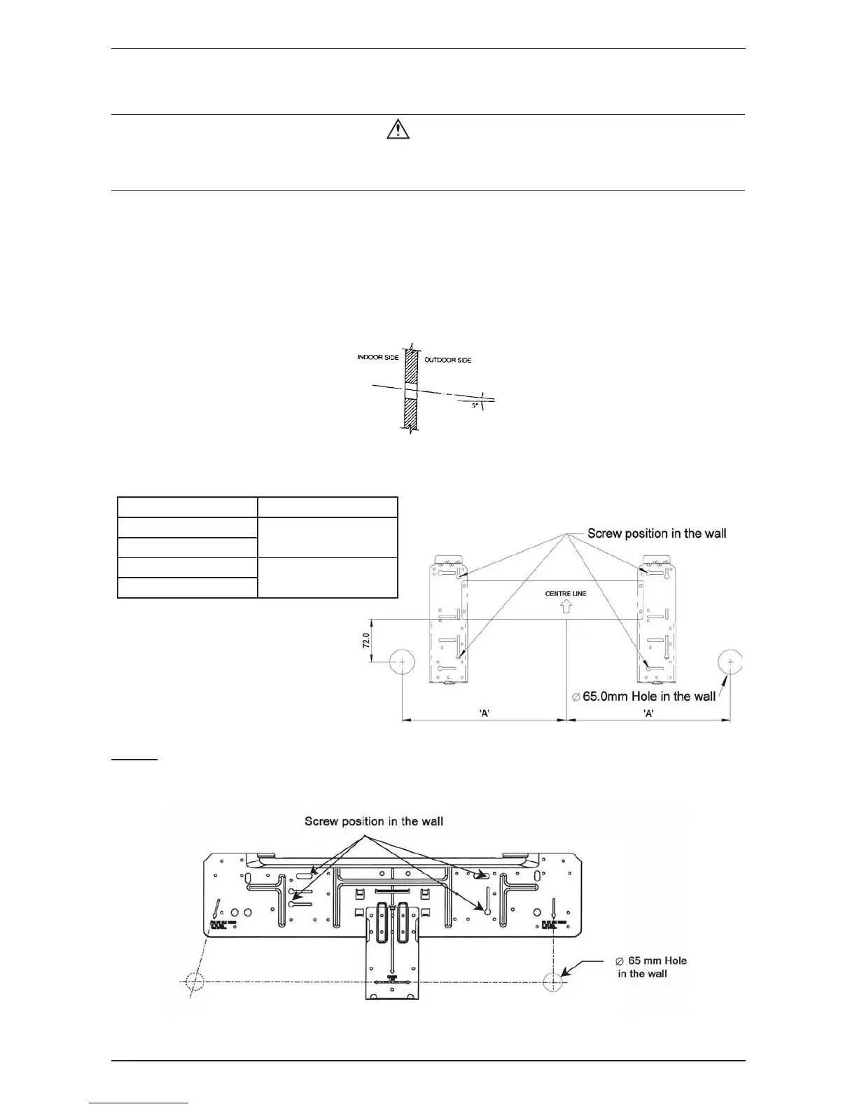
Drill the pipe hole at the location as per plan. (This is only applicable for rear piping outlet installation).
Note: The hole should be drilled slightly lower at outdoor side as per fi gure below:--
Fix the installation plate fi rmly to wall, without tilting to left or right. Use a plumb line, if available.
•
•
•
•
•
Model DIMENSION “A”
AWM 07/09 G/GR
350.0 mm
A5WM 07/09 G/GR
AWM 10/15 G/GR
400.0 mm
A5WM 10/15 G/GR
MODEL
AWM 20 / 25 G/GR, A5WM 20 / 25 G/GR, AWM 30F / 30FR, A5WM 31F / 30FR
 Loading...