EasyManua.ls Logo

Actron Global OBD II Scan Tool 9620 User Manual

Default Icon
18 pages
To Next Page IconTo Next Page
Page #1 background imageLoading...
Page #1 background image
9620 Global
OBD II Scan Tool
©2002 Actron Manufacturing Co.
Printed in USA
0002-002-2361
ACTRON MANUFACTURING CO.
15825 Industrial Parkway
Cleveland, Ohio 44135-9946
USA
Internet and e-mail - http://www.actron.com
SFI or SEFI:
Sequential Fuel Injection or Sequential Electronic Fuel Injection. A fuel injection system
that uses one or more injectors for each cylinder. The injectors are mounted in the
intake manifold and are fired individually.
ST:
Short Term fuel trim.
TBI:
Throttle Body Injection. A fuel injection system having one or more injectors mounted in a
centrally located throttle body, as opposed to positioning the injectors close to an intake
valve port. TBI is also called Central Fuel Injection (CFI) in some vehicles.
TDC:
Top Dead Center. When a piston is at its uppermost position in the cylinder.
Throttle Body:
A device which performs the same function as a carburetor in a fuel injection system. On a
throttle body injection (TBI) system, the throttle body is both the air door and the location of
the fuel injectors. On port fuel injection systems (PFI, MPFI, SFI, etc.), the throttle body is
simply an air door. Fuel is not added until the injectors at each intake port are activated. In
each case, the throttle body is attached to the accelerator pedal.
TPS:
Throttle Position Sensor. Potentiometer-type sensor connected to the throttle shaft. Its voltage
signal output increases as the throttle is opened. The PCM uses this signal to control many
systems such as idle speed, spark advance, fuel delivery, etc.
TTS:
Transmission Temperature Sensor. A resistance sensor mounted in the transmission
housing in contact with the transmission fluid. It sends a voltage signal to the PCM indicating
the temperature of the transmission.
VECI:
Vehicle Emission Control Information. A decal located in the engine compartment containing
information about the emission control systems found on the vehicle. The VECI is the
authoritative source for determining whether a vehicle is OBD II-compliant.
VIN:
Vehicle Identification Number. This is the factory-assigned vehicle serial number. This
number is stamped on a number of locations throughout the vehicle, but the most prominent
location is on top of the dashboard on the drivers side, visible from outside the car. The VIN
includes information about the car, including where it was built, body and engine codes,
options, and a sequential build number.
VSS:
Vehicle Speed Sensor. Sends a frequency signal to the PCM. The frequency increases as
the vehicle moves faster to give the PCM vehicle speed information used to determine shift
points, engine load, and cruise control functions.
WOT:
Wide-Open Throttle. The vehicle operating condition brought about when the throttle is
completely (or nearly) open. The PCM will typically deliver extra fuel to the engine and de-
energize the A/C compressor at this time for acceleration purposes. The PCM uses a
switch or the Throttle Position Sensor to identify the WOT condition.
Question and Answer IconNeed help?

Do you have a question about the Actron Global OBD II Scan Tool 9620 and is the answer not in the manual?

Actron Global OBD II Scan Tool 9620 Specifications

General IconGeneral
Product TypeOBD II Scan Tool
Model Number9620
DisplayColor LCD
Power SourceVehicle battery
CompatibilityOBD II compliant vehicles (1996 and newer)
ConnectivityWired
FeaturesLive data, Freeze frame data

Summary

Vehicle Service Information

Service Manuals

Lists publishers of manuals containing electronic engine control diagnostic information.

Manufacturer Service Manuals

Lists service manuals for specific vehicle manufacturers like GM, Ford, and Chrysler.

Safety Precautions

General Safety Guidelines to Follow When Working on Vehicles

Provides essential safety rules and procedures to prevent injury or damage during vehicle testing.

Section 1: Vehicle Computer Systems

1.1 Introduction

Introduces vehicle computer control systems, sensors, and their role in engine management.

Appendix B: Glossary & Definitions

Provides alphabetical listing of terms and definitions related to vehicle diagnostics.

1.2 Data Link Connector and Location

Describes the Data Link Connector (DLC), its purpose, and typical location in a vehicle.

1.3.1 Keyboard

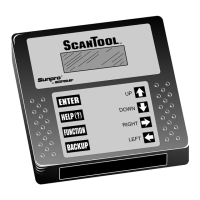
Details the functions of the scan tool's keyboard for navigation and operation.

1.3.2 Display

Explains the scan tool's LCD display capabilities and on-screen symbols.

1.3.3 Lists, Menus, and Questions

Describes how to navigate menus and respond to questions on the scan tool.

1.4 Tool Setup

Explains how to configure scan tool settings like units and display contrast.

1.4.1 Changing Measurement Units

Guides users through changing measurement units between English and Metric.

1.4.2 Changing Display Contrast

Details how to adjust the contrast of the scan tool's display for readability.

1.4.3 Displaying Tool Information

Shows how to view the scan tool's serial number, software ID, and hardware version.

1.4.4 Program Mode

Explains how to use program mode for scan tool software updates.

1.5 Personal Computer (PC) and Printer Interface

Describes connecting the scan tool to a PC or printer for software updates and printing.

1.6 Replacing the Battery

Instructions for replacing the internal 9V battery of the scan tool.

1.7 AC Adapter

Specifications for using an AC adapter to power the scan tool.

Section 2: Diagnosing with the Scan Tool

2.1 Preliminary Checks

Visual inspection steps to perform before using the scan tool for diagnosis.

2.2 Connecting the Scan Tool

Step-by-step guide on how to connect the scan tool to the vehicle's DLC.

4.3 Tool Self-Tests

Instructions for performing self-tests on the scan tool's display, keyboard, and memory.

4.3.1 Display Test

Guides the user through testing all pixels on the scan tool's display.

4.3.2 Keyboard Test

Details how to test the functionality of each key on the scan tool.

4.3.3 Memory Test

Describes how to perform a test on the scan tool's internal memory.

4.3.4 Printer Test

Instructions for testing the scan tool's ability to print data.

4.4 Technical Support

Contact information and advice for obtaining technical support for the scan tool.

2.3 OBD II Functions List

Lists the available functions of the OBD II scan tool for vehicle diagnostics.

4.2.3 One or more modules drops the communication link

Explains what to do if vehicle modules lose communication during a scan.

4.2.4 Keyboard does not function properly

How to test and troubleshoot keyboard functionality on the scan tool.

4.1 How to Use Help

Explains how to access help screens for functions, errors, and on-screen symbols.

4.2.1 Scan Tool does not power up

Troubleshooting steps if the scan tool fails to power up or shows no power.

4.2.2 Scan Tool does not "Link" with vehicle

Steps to resolve issues when the scan tool cannot establish communication with the vehicle.

Section 3: Diagnostic Trouble Codes (DTC)

3.3 Diagnostic Trouble Code Ranges

Details the code ranges assigned to specific vehicle systems and categories.

3.2 Code Lookup

Describes how to look up definitions of Diagnostic Trouble Codes stored in the scan tool.

3.1 DTC Format

Explains the alphanumeric format and types of Diagnostic Trouble Codes (DTCs).

Related product manuals