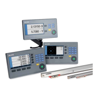
The ACU-RITE digital readouts are designed to enhance the profitability and productivity of manually operated machine tools, while also improving the quality of machined workpieces. These readouts feature a 7-inch TFT color flat panel display that clearly shows actual axis positions. Context-sensitive graphical user guidance simplifies operation, making the ACU-RITE digital readouts user-friendly. When paired with ACU-RITE linear scales, they form an economical and effective package solution for both initial setup and retrofitting of machine tools.
DRO100 - Simple Digital Readout for One, Two, or Three Axes
The DRO100 is well-suited for general applications on milling, drilling, boring, and lathe machines with one, two, or three axes. Its sturdy housing and splash-proof membrane keyboard make it ideal for workshop environments. The 7-inch TFT color screen displays position values, status information, and other useful data. Key functions are quickly accessible via dedicated function keys. For lathes, users can easily switch between radius and diameter display. The 3-axis version offers a sum display feature, allowing the saddle and top slides to be viewed either together or separately. A USB port facilitates data and file transfer.
Technical Specifications (DRO100):
- Axes: 1, 2, or 3 (selectable upon ordering)
- Encoder Inputs: TTL
- Display Step: Adjustable, max. 7 digits (Linear axis: 1 mm to 0.0001 mm; Rotary axis: 1° to 0.001° (00° 00′ 01″)). Depends on the signal period of the connected encoder.
- Display: 7-inch TFT color screen (15:9 aspect ratio); 800 x 400 pixels resolution for position values and dialog.
- Status Display: Freed rate, ABS/INC, mm/inch.
- Functions: 1 datum, REF reference-mark evaluation (distance-coded or single reference marks), Distance-to-go mode, mm/inch switching, Absolute-incremental display, Integrated help function, Axis coupling, Radius/diameter display.
- Error Compensation: Linear axis error.
- Data Interface: USB connection, Type C.
- Optional Accessories: Stand, holder for mounting arm, protective cover.
- Power Connector: AC 100 V (-10%) to 240 V (+5%), 50 Hz to 60 Hz (±5%), 33 W.
- Operating Temperature: 0 °C to 45 °C (storage temperature -20 °C to 70 °C).
- Protection: IP 40 (front panel IP 54).
- Mass: 1.6 kg.
DRO203 - Versatile Digital Readout for Up to Three Axes
The DRO203 is specifically designed for milling, drilling, boring, and lathe machines with up to three axes. It features a sturdy upright unit with a splash-proof full-travel keypad, suitable for workshop use. The 7-inch TFT color screen provides position values, dialogs, input displays, graphic functions, and a graphic positioning aid. The Klartext dialog guidance simplifies operation, and the distance-to-go display aids in quick and reliable positioning by traversing to zero. Special functions include hole patterns (linear and circular). For turning, it allows easy switching between radius and diameter display, and a sum display for lathes with a separate top slide. Presets can be set by touching the workpiece and freezing the tool position, then retracting and measuring. A USB port enables data and file transfer.
Technical Specifications (DRO203):
- Axes: 2 or 3 (configurable); various axis designations (selectable upon ordering).
- Encoder Inputs: TTL.
- Display Step: Adjustable, max. 7 digits (Linear axis: 1 mm to 0.0001 mm; Rotary axis: 1° to 0.001° (00° 00′ 01″)). Depends on the signal period of the connected encoder.
- Display: 7-inch TFT color screen (15:9 aspect ratio); 800 x 400 pixels resolution for position values and dialog.
- Status Display: Tool, reference point, operating function, feed rate, ABS/INC, mm/inch, stopwatch.
- Functions: 10 reference points, 16 tools, REF reference-mark evaluation (distance-coded or single reference marks), Distance-to-go mode, Scaling factor, mm/inch switching, Absolute-incremental display, Integrated help function, Graphic positioning aid ("near zero" warning), Calculator.
- For Milling/Drilling/Boring: Calculation of positions for hole patterns (bolt circles, linear hole patterns), Tool radius and tool length compensation, Linear hole patterns, bolt hole circles.
- For Turning: Taper calculator, Radius/diameter switching, Freezing the tool position for back-off, Vectoring (X/Y display of traverse path with inclined top slide), Sum display for Z and Zo (axis coupling).
- Error Compensation: Axis error (Linear and multipoint over up to 200 points), Backlash compensation (for compensation of reversal error).
- Data Interface: USB connection, Type C.
- Accessories: Stand, holder for mounting arm, protective cover.
- Power Connector: AC 100 V (-10%) to 240 V (+5%), 50 Hz to 60 Hz (±5%), 33 W.
- Operating Temperature: 0 °C to 45 °C (storage temperature -20 °C to 70 °C).
- Protection: IP 40 (front panel IP 54).
- Mass: 1.7 kg.
DRO300 - Programmable Digital Readout for Three or Four Axes
The DRO300 is a versatile digital readout primarily designed for milling, drilling, boring, and lathe machines with up to four axes. It features a splash-proof full-travel keyboard, making it exceptionally well-suited for workshop use. The large, easy-to-read color flat-panel display supports all operations with intuitive interactive menus. The DRO300 includes all functions of the DRO203. Additionally, it offers a connection for the KT 130 edge finder, enabling precise definition of presets and datums with special probing functions. The DRO300 is programmable, ideal for small-batch production on conventional machine tools, allowing storage of up to eight programs, each with up to 250 working steps. Programs can be created by keying in steps or by generating them through actual position capture (teach-in programming). A separate I/O unit provides switching inputs/outputs for simple automation tasks. A USB port enables data and file transfer.
Technical Specifications (DRO300):
- Axes: 3 or 4; various axis designations.
- Encoder Inputs: TTL.
- Display Step: Adjustable, max. 7 digits (Linear axis: 1 mm to 0.0001 mm; Rotary axis: 1° to 0.001° (00° 00′ 01″)). Depends on the signal period of the connected encoder.
- Display: 7-inch TFT color screen (15:9 aspect ratio); 800 x 400 pixels resolution for position values and dialog.
- Status Display: Tool, reference point, operating function, feed rate, ABS/INC, mm/inch, stopwatch.
- Axis Display: Switchable between DRO1 and DRO2.
- Functions: 10 reference points, 99 tools, REF reference-mark evaluation (distance-coded or single reference marks), Distance-to-go mode, Scaling factor, mm/inch switching, Absolute-incremental display, Integrated help function, Graphic positioning aid ("near zero" warning), Calculator.
- For Milling/Drilling/Boring: Calculation of positions for hole patterns (bolt circles, linear hole patterns), Tool radius and tool length compensation, Probing functions for reference-point acquisition with KT edge finder ("Edge," "Centerline," and "Circle center"), Oblique line, circular arc, Linear hole patterns, bolt hole circles.
- For Turning: Taper calculator, Radius/diameter switching, Freezing the tool position for back-off, Vectoring (X/Y display of traverse path with inclined top slide), Sum display for Z and Zo (axis coupling).
- Programming: 8 programs with up to 250 steps.
- Error Compensation: Axis error (Linear and multipoint over up to 200 points), Backlash compensation (for compensation of reversal error).
- Data Interface: USB connection, Type C.
- Switching I/O: Input for edge finder, Further inputs/outputs over the IOB 610 external input/output unit.
- Accessories: Stand, holder for mounting arm, protective cover, KT 130 edge finder (for milling).
- Power Connection: AC 100 V (-10%) to 240 V (+5%), 50 Hz to 60 Hz (±5%), ≤ 33 W.
- Operating Temperature: 0 °C to 45 °C (storage temperature -20 °C to 70 °C).
- Protection: IP 40 (front panel IP 54).
- Mass: 1.7 kg.
The IOB 610 unit (ID 1197271-01) provides application-dependent additional functions when connected to the DRO300. It attaches to a standard NS 35 rail. Connection to the DRO300 is via the touch probe input. LEDs indicate power supply, data transmission, and input/output status.
IOB 610 Specifications:
- 6 Switching Inputs: Zero reset of axes 1 to 4 (milling), Recognition of max. 4 gear ranges (turning), External activation of CSS (turning).
- 10 Switching Outputs: 9 relay outputs as switching functions (milling), 1 relay output for readiness.
- 1 Analog Output: 0 V to 10 V (Turning: constant surface speed; Milling: controlling spindle speed).
- Voltage Supply: Via DRO300.
- Cable Length: ≤ 4 m to DRO300.
- Storage Temperature: 20 °C to 70 °C.
- Operating Temperature: 0 °C to 45 °C.
Linear Encoders
ACU-RITE offers linear encoders for manually operated machine tools, including the SENC 50 and SENC 150 series.
- SENC 50: Compact linear encoder for limited installation space, ideal for lathe slides. Provides display steps of 10 µm without interpolation for typical applications, or 1 µm and better with 5-fold or 10-fold interpolation for higher requirements.
- SENC 150: Standard linear encoder for universal linear encoder applications under normal mounting conditions. Provides display steps of 10 µm without interpolation for typical applications, or 1 µm and better with 5-fold or 10-fold interpolation for higher requirements.
SENC 50 Technical Specifications:
- Measuring Standard: Glass scale with incremental graduation.
- Accuracy Grade: ±3 µm.
- Measuring Length ML*: 50 mm to 525 mm (mounting spar optional).
- Incremental Signals*: TTL, TTL x 5, TTL x 10.
- Grating Period: 20 µm.
- Integrated Interpolation: Without, 5-fold, 10-fold.
- Signal Period: 20 µm, 4 µm, 2 µm.
- Measuring Step¹: 5 µm, 1 µm, 0.5 µm.
- Reference Marks: Distance-coded.
- Voltage Supply (Without Load): DC 5.1 V ±0.1 V/< 180 mA (TTL), DC 5.1 V ±0.1 V/< 220 mA (TTL x 5, TTL x 10).
- Electrical Connection: Cable in metal armor, with 9-pin D-sub connector; length: 3 m.
- Cable Length: ≤ 6 m (total length with ACU-RITE cable).
- Traversing Speed: ≤ 60 m/min.
- Required Moving Force: ≤ 2.2 N.
- Operating Conditions: Temperature 0 °C to 50 °C; humidity 25% to 95% (non-condensing).
- Conditions for Storage: Temperature -20 °C to 70 °C; humidity 20% to 95% (non-condensing).
- Protection: IP53 when mounted as per Mounting Instructions.
- Mass: 0.5 kg + 0.3 kg/m measuring length.
SENC 150 Technical Specifications:
- Measuring Standard: Glass scale with incremental graduation.
- Accuracy Grade: ±5 µm.
- Measuring Length ML*: 50 mm to 3075 mm (mounting spar optional for lengths up to 1550 mm, included for 1675 mm and above).
- Incremental Signals*: TTL, TTL x 5, TTL x 10.
- Grating Period: 20 µm.
- Integrated Interpolation: Without, 5-fold, 10-fold.
- Signal Period: 20 µm, 4 µm, 2 µm.
- Measuring Step¹: 5 µm, 1 µm, 0.5 µm.
- Reference Marks: Distance-coded.
- Voltage Supply (Without Load): DC 5.1 V ±0.1 V/< 180 mA (TTL), DC 5.1 V ±0.1 V/< 220 mA (TTL x 5, TTL x 10).
- Electrical Connection: Cable in metal armor, with 9-pin D-sub connector; length: 4 m (or 6 m for 1250 mm measuring length or more).
- Cable Length: ≤ 9 m (total length with ACU-RITE cable).
- Traversing Speed: ≤ 60 m/min.
- Required Moving Force: ≤ 3.4 N.
- Operating Conditions: Temperature 0 °C to 50 °C; humidity 25% to 95% (non-condensing).
- Conditions for Storage: Temperature -20 °C to 70 °C; humidity 20% to 95% (non-condensing).
- Protection: IP53 when mounted as per Mounting Instructions.
- Mass: 0.65 kg + 0.7 kg/m measuring length.
Usage Features:
- Installation Guide (DRO203, DRO300): A step-by-step guide for initial configuration, including encoder selection and parameter adoption. Further settings like scaling factor and error compensation can be configured separately.
- Probing Functions for Presets (DRO300): Utilizes the HEIDENHAIN KT edge finder for easy datum setting. The readout automatically stores exact positions, accounting for approach direction and stylus/tool radius. Functions include workpiece edge, centerline, and circle center as datums.
- Tool Compensations (DRO203, DRO300): Tool data (diameter and length) can be saved in a tool table. Data can be from preset tools or measured on the machine. In distance-to-go mode, the readout compensates for tool radius and length.
- Distance-to-Go Display (DRO100, DRO203, DRO300): Simplifies work by displaying the remaining distance to a target position. For milling, it compensates for the milling radius, allowing direct use of drawing dimensions. Includes a "near zero" message with a square cursor for precise positioning.
- Dynamic Zoom (DRO203, DRO300): Enhances position value readability by maximally enlarging the display value for the currently moving axis in four steps. Character height can increase from 17 mm to 25 mm for small numbers. The display returns to standard size after a second of no movement.
- Hole Patterns (DRO203, DRO300): Automatic calculation of circular and linear hole patterns for milling and drilling. Users enter geometric dimensions and number of holes, and the display calculates coordinates. A graphic display verifies input before machining.
- Programming of Machining Steps (DRO300): Allows saving repetitive machining steps as programs (up to 8 programs with 250 steps each). Programs can be created by typing positions or using actual position capture (teach-in). Fixed cycles (Bolt Hole Circle, Linear Hole Pattern, Incline Mill Form, Circular Arc) shorten programming time.
- Assistance for Working with Lathes (DRO203, DRO300, DRO303):
- Radius/Diameter Display: Switch between radius and diameter values for the transverse axis.
- Sum Display of Longitudinal Axes: Displays saddle and top slide positions separately or as a sum. Sum display adds both values algebraically for absolute tool position relative to workpiece datum.
- Vectoring (DRO203, DRO300): Breaks down movement into longitudinal and crossfeed axis components, useful for turning threads (e.g., seeing thread diameter in X-axis while moving compound axis handwheel).
- Taper Turning Made Easy (DRO203, DRO303): Integrated taper calculator helps determine the correct angle for the top slide by entering taper ratio, two diameters, and length.
- Constant Surface Speed (DRO300): Controls spindle speed based on workpiece diameter via the IOB 610 output module, optimizing machining results and tool life.
Maintenance Features:
- Error Compensation: Linear and multipoint axis error compensation (up to 200 points) and backlash compensation for reversal error.
- General Electrical Information: Guidelines for electrical noise immunity and protection, including using original ACU-RITE cables, metal-housed connecting elements, proper shield grounding, and maintaining adequate spacing from interference sources. Power supply should be from PELV systems (EN 50 178) with high-frequency grounding.