Do you have a question about the ADEMCO 4281 Series and is the answer not in the manual?
Overview of ADEMCO RF receivers and their compatibility with control panels.
Instructions and considerations for installing ADEMCO RF receivers, including spatial diversity.
Specific mounting and usage instructions for the 5881EH in commercial fire systems.
Configuration of receiver addresses and special functions using DIP switches.
Details on dimensions, input voltage, current, and range for RF receivers.
Guidance for installers on maintenance, testing, and user training.
Information regarding FCC regulations, potential interference, and user guidance.
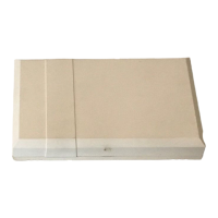
Visual guide for mounting the receiver circuit board within a control cabinet.
Diagrams and tables for wiring, model identification, and key features.
Detailed explanation of DIP switch functions and receiver address settings.
Discussion of factors affecting system performance, potential failures, and sensor limitations.
Details the terms, duration, exclusions, and seller's liability for ADEMCO products.
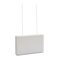
The ADEMCO 4281/5881/5882 Series RF Receivers are designed for use with control panels that support an RF receiver connection via remote keypad connection points. These receivers recognize alarm, status, and keypad control messages from wireless transmitters. The 4281/4281CN series operates at 345MHz (in Canada, 315MHz), while the 5881/5882 series operates at 345MHz. The various versions of these receivers are generally referred to as "receiver" unless otherwise specified.
The primary function of these RF receivers is to receive signals from wireless transmitters and relay them to a control panel. This allows for the integration of wireless security devices, such as intrusion detectors, into a larger alarm system. The receivers feature a Spatial Diversity System, which is designed to virtually eliminate "Nulls" and "Dead Spots" within the coverage area, ensuring more reliable signal reception.
The 4281/4281CN family of receivers is used with 5700 series transmitters, while the 5881/5882 family is used with 5800 series transmitters. The 5881EH is an enhanced version of the 5881H, incorporating Ademco's SignalSentry™ technology for high-security wireless transmissions, specifically intended for commercial fire installations. For commercial fire applications, the 5881EH must be used with control panels approved for such use.
The document includes a comprehensive "WARNING: THE LIMITATIONS OF THIS WIRELESS ALARM SYSTEM" section, highlighting that while the system is advanced, it does not offer guaranteed protection. Key limitations include: