14
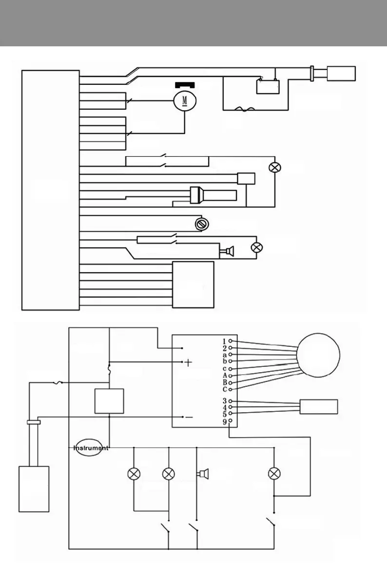
Electrical schematic diagram
II.Chain adjustment (see figure 4)
1.Loosen the rear axle left and right fastening nuts, adjust the chain regulator, move the rear
wheels back and forth, and tighten the tightness of the chain so that the sag in the middle of the
chain is 10-15mm.At this time, the tightness of the chain should be suitable for go slick, no
abnormal sound.
2.Keep the center surface of the rear wheel basically in the center surface of the frame, and tighten
the rear axle left and right fastening nuts. (Recommended torque is not less than 30N.m)
III.Front wheel disassembly (see Figure 5)
1.Loosen the left and rear fastening thread of the front axle, remove the nut, remove the front
axle, and remove the front wheel.
2.When assembling, align the center hole of the front wheel with the double arm hole of the
hydraulic front fork, penetrate the front axle into the hole, and tighten the left and right fastening
nuts of the front axle clock wise. After installation, rotate the front wheel, and there shall be no
stuck or loose phenomenon. (The recommended torque is not less than 18N. m)
IV.Rear wheel disassembly (see Figure 6)
1.Pull the motor cable off the connector, turn the car body over(note: Do not touch the handlebar,
head cover, toolbox parts), rotate the rear axle nut, rear brake positioning nut and brake cable in
the counterclockwise direction, unpack the chain joint, and then remove the rear wheel in the
direction of the opening.
Power negative P+
Motor line
Motor Hall
Front brakes handle power-off switch
Rear brake handle power-off switch
three-way switch
Transfer handle
Headlight switch
speaker switch
Anti-theft
device+
Power supply
electric door lock
Charger
Rear Light
dipped
headlight
Horn
brake lamp
Brake broken wire
Speeder
Contraller
30A fuse
Batter
M
Brake handle
+
-
ACC
A3
w
F5
electric door lack
Headlight
Taillight
Fuse
Fuse
Battery
Charger
charging interface
5A
Controll
 Loading...