q - a
1 0 0 0
1-22
p - c
1 0 0 0
1-21
p - b
1 0 0 0
1-20
p - a
1 0 0 0
1-19
p f - c
) 9 8 0
1-18
) 9 8 0
p f - b
1-17
p f - a
) 9 8 0
1-16
2 9 ( 9 9
I - c
1-15
2 9 ( 9 9
I - b
1-14
2 9 ( 9 9
I - a
1-13
3 7 & 5
u - c
1-12
3 8 ) 5
u - b
1-11
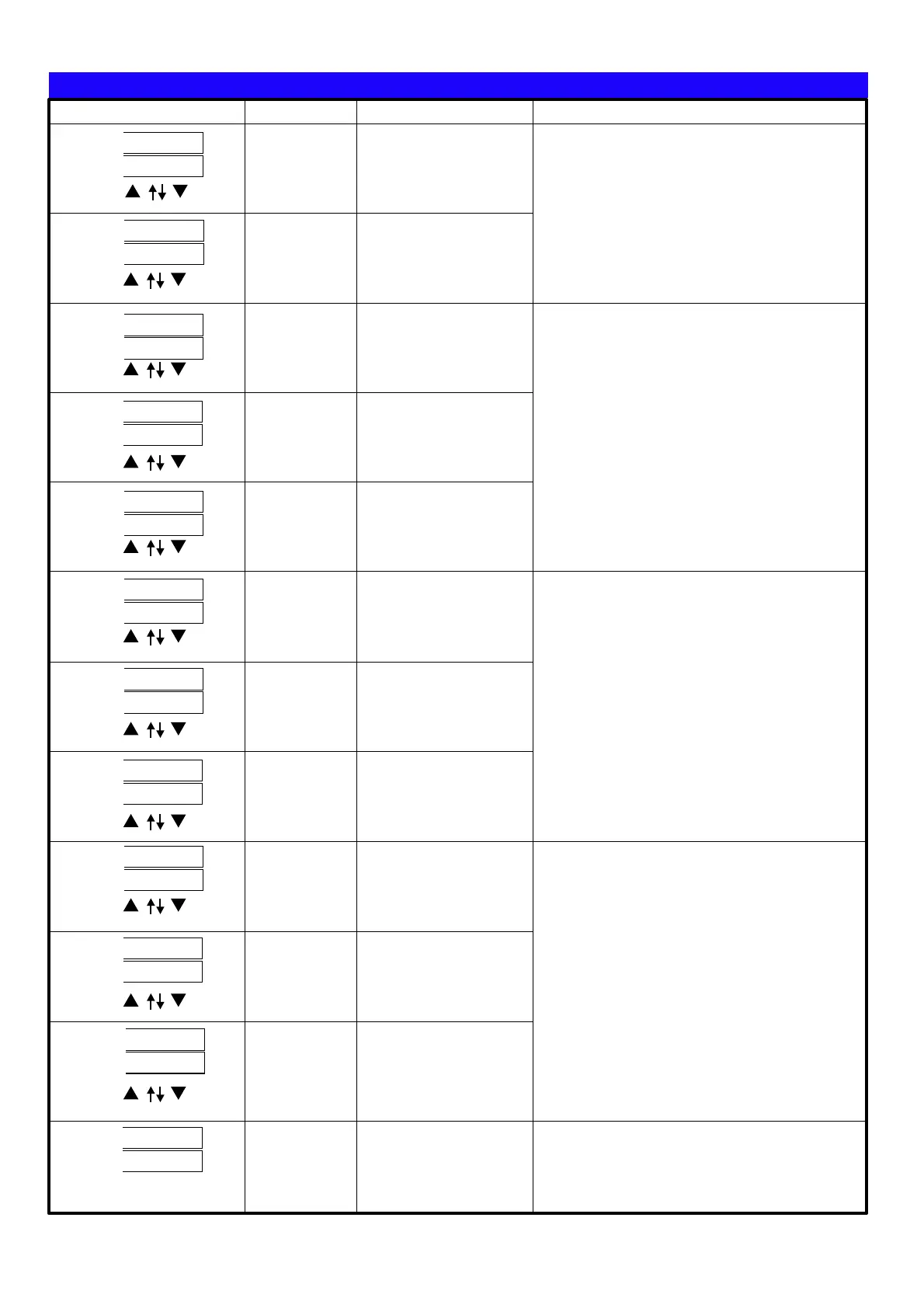
User Level
■Operating Steps
1 /3 24
Parameters
Display
Setting
Operation
B Phase
voltage
C Phase
voltage
View only
View only
Each phase voltage refers to the relative N and
white voltage。 Va(Vb、Vc)with Vn
voltage。3P4W wiring, only to show the line
voltage of N, if you want to understand the line to
line voltage, is only the value multiplied by
1.732.。
3P3W wiring, S need to short circuit and N, so the
only Vab and Vca value and read value is the line
voltage。
Reading needs with the unit KV or V。
A Phase
current
View only
B Phase
current
View only
C Phase
current
View only
Each phase current is flowing through the line
current Ia Ib Ic current。 、 、 。
Current unit is ampere。
A Phase
power
factor
B Phase
power
factor
C Phase
power
factor
View only
View only
View only
A Phase
active
power
View only
B Phase
active
power
View only
C Phase
active
power
View only
3P3W system, the system in “a phase current
lag behind voltage 30 degree angle, "and" c
phase current leads the voltage 30 degree angle
", so the total power factor of 1.00, PF-A will be
= 0.866, PF-C will be = -0.866, so the display is a
normal phenomenon。
Reading needs with the unit MW, KW or W。
A Phase
reactive
power
View only
En d te rm in al o hm
ADEFGHI -1,:JKL)*MNO.PQNOMRS.<)
*3 4RSTUVWP4W.3
)*1 2 4,1-10~1-27XYZRSP W
)*1 4,1-14/1-1 ~ XYZRSP3W 6 27
)*3 4,1-1 1-1 /1-1 1- /P3W.1 3~ 5 7/1-18/ 20 1-21/1-23/1-24/1-
26/1-27XYZRS
)*3 4,1-1 1- /1- XYZRSP3W.2 7/ 20 23/1-26
)*3 4,1-1 1- /1- XYZRSP3W.3 7/ 20 23/1-26
)*3 4,1-1 1- /1-P4W.1 4~15/ 17~18 20~21/1-23~24/1-26~27
XYZRS
)*+,:1 p 2 w 1 p 3 w 3 p 3 w .1 3 p 3w .2 3p 3w .3/ / / / /
3 p 4 w .1 3 p 4 w .3/
"#$%&':
v a v g. ()*+,-.:
i a v g. ()*/,-.:
f r e q :
2345.
p . t l :()673.
q . t l :()6873.
s . t l :()69:73.
p f . a vg :(),-73;
%45.
v a : )*+.45A
vb :B)*+.45
vc :C)*+.45
ia :A)*/.45
ib :B)*/.45
ic :C)*/.45
p f - a :A)7345.
pf-b :B)7345.
pf-c :C)7345.
p - a :A)7345.
p-b :B)7345.
p-c :C)7345.
q - a :A)87345.
q-b :B)87345.
q-c :C)87345.
s - a :A)9:7345
s - b :B)9:7345
s - c :C)9:7345
RELAY / PULSE output of the outputs can
only choose a functional output
EX: Select PULSE output and then RELAY
function no output and vice versa
Clamp CT
Optional of Clamp CT, make sure
(1)CT of the SN number with the
CPM-10 SN number, as shown
( )2 On the label
A A Phase B B: - ; : -
Phase C C Phase; : - ;
According to the phase matching
Relay Pulse output
CL
BK
AK
AL
BL
CK
, ,0123CT4 56789:; <=>?@A
 Loading...