24 24/
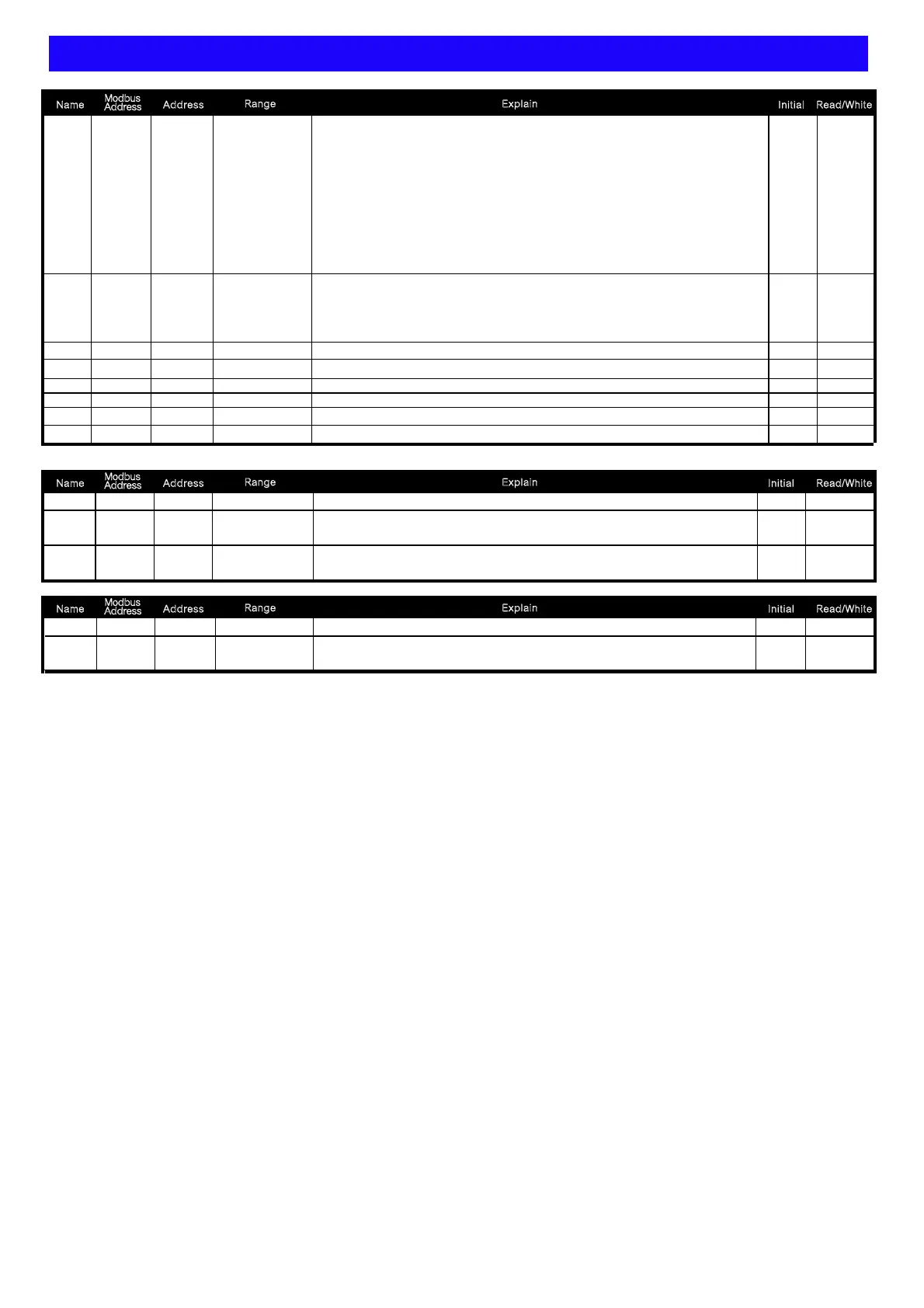
CPM-10 MODBUS ADDRESS TABLE**Address number are Hexadecima
The parameter relative to Analog Output 1
0: Average Voltage 1: Average Current 2: Frequency 3: Total Active Power
4: Total Re-active Power 5: Total Apparent Power 6: Average Power Factor
7: Phase-A Voltage 8: Phase-B Voltage 9: Phase-C Voltage
10: Phase-A Current 11: Phase-B Current 12: Phase-C Current
13: Phase-A Power Factor 14: Phase-B Power Factor 15: Phase-C Power Factor
16: Phase-A Active Power 17: Phase-B Active Power 18: Phase-C Active Power
19: Phase-A Re-active Power 20: Phase-B Re-active Power
21: Phase-C Re-active Power 22: Phase-A Apparent Power
23: Phase-B Apparent Power 24: Phase-C Apparent Power
Analog Output 1 Low scale
Analog Output 1 Type
RS485 parity
RS485 address
RS485 baud rate
Pulse Devider
The Period of Pulse Output High
Analog Output 1 High scale
Analog Output Zero adjustment
Analog Output Span adjustment
The clear of Analog Output Zero and Span
Analog Output High Limit
ao.sl
0~24 R/W
0: V.0-5 1: V.1-5 2: V.0-10 3: V.0.b.5 4: V.1.b.5
5:V.0.b.10 6: V.b.5 7: V.b.10
8: A.0-10 9: A.0-20 10: A.4-20 11: A.4.b.20 12: A.b.10 13: A.b.20
ao.ls
-19999~29999 R/W
ao.hs
-19999~29999
R/W
ao.tp
0~13
R/W
adres
1~255 1 R/W
R/W
0: 1200 1: 2400 2: 4800 3: 9600 4: 19200 5: 38400
prity
0~3 1 R/W
0: n-8-1 1: n-8-2 2: odd 3: even
baud
0~5 3
plSdv
1~9999 1 R/W
R/W
0(Auto)/~1~5000*4mSec
plShi
0~5000 0
ao.zo
ao.sn
zSclr
aOlt
R/W
R/W
R/W
R/W
-32168~32767
-32168~32767
0~3
0~11000
007CH
007DH
0070H
0071H
0072H
0054H
0053H
0052H
0051H
0050H
004FH
004EH
004DH
40125
40126
40113
40114
40115
40078
40079
40080
40081
40082
40083
40084
40085
1100
0
0
0
3000
0
10
0
Name
Address
Range
Read/White
Initial
Explain
Modbus
Address
Name
Address
Range
Read/White
Initial
Explain
Modbus
Address
Name
Address
Range
Read/White
Initial
Explain
Modbus
Address
En d te rm in al o hm
ADEFGHI -1,:JKL)*MNO.PQNOMRS.<)
*3 4RSTUVWP4W.3
)*1 2 4,1-10~1-27XYZRSP W
)*1 4,1-14/1-1 ~ XYZRSP3W 6 27
)*3 4,1-1 1-1 /1-1 1- /P3W.1 3~ 5 7/1-18/ 20 1-21/1-23/1-24/1-
26/1-27XYZRS
)*3 4,1-1 1- /1- XYZRSP3W.2 7/ 20 23/1-26
)*3 4,1-1 1- /1- XYZRSP3W.3 7/ 20 23/1-26
)*3 4,1-1 1- /1-P4W.1 4~15/ 17~18 20~21/1-23~24/1-26~27
XYZRS
)*+,:1 p 2 w 1 p 3 w 3 p 3 w .1 3 p 3w .2 3p 3w .3/ / / / /
3 p 4 w .1 3 p 4 w .3/
"#$%&':
v a v g. ()*+,-.:
i a v g. ()*/,-.:
f r e q :
2345.
p . t l :()673.
q . t l :()6873.
s . t l :()69:73.
p f . a vg :(),-73;
%45.
v a : )*+.45A
vb :B)*+.45
vc :C)*+.45
ia :A)*/.45
ib :B)*/.45
ic :C)*/.45
p f - a :A)7345.
pf-b :B)7345.
pf-c :C)7345.
p - a :A)7345.
p-b :B)7345.
p-c :C)7345.
q - a :A)87345.
q-b :B)87345.
q-c :C)87345.
s - a :A)9:7345
s - b :B)9:7345
s - c :C)9:7345
RELAY / PULSE output of the outputs can
only choose a functional output
EX: Select PULSE output and then RELAY
function no output and vice versa
Clamp CT
Optional of Clamp CT, make sure
(1)CT of the SN number with the
CPM-10 SN number, as shown
( )2 On the label
A A Phase B B: - ; : -
Phase C C Phase; : - ;
According to the phase matching
Relay Pulse output
CL
BK
AK
AL
BL
CK
, ,0123CT4 56789:; <=>?@A
 Loading...