4
Control button
Enter / Shift / Up / Down
Up key:
Increase
/
back to previous
Down key:
Decrease
/
to next
Shift key:
Change decimal
/
back to previous
or escape setting
Enter/Fun key: Enter setting
/
save changes and
enter next parameters
P L S
COM
RL1
Display digits
Operation button
LED status
Pulse output: 1 rectangular red LED , when
pulse output LED blink;blink
faster mean more active energy
used.
RS 485 Com. rectangular orange LED when: 1 ,
Rs send receive data LED485 / ,
blink´blink faster mean data
transfer
Relay: 1 rectangular red LED,LED light
when relay energized ECI input
PV values 5 digits 0.28 0.71cm red LED: ; ”( )
Accumulative values 10 digits 0.28 cm; ”(0.71 )
K V
WH
LED Unit
Voltage unit LED rectangular red LED indicate:2
KV or V ,on when display select V-A
Watt unit LED Rectangular green LED , on when:3
display select KWH, automatic
switch KW or MW units
active energy LED rectangular red LED, on: 1
when select KWH display , only
display WH, K/M unit follow Watt.
Current unit LED rectangular red LED, on when:1
select display V-A
V
A
M
K
W
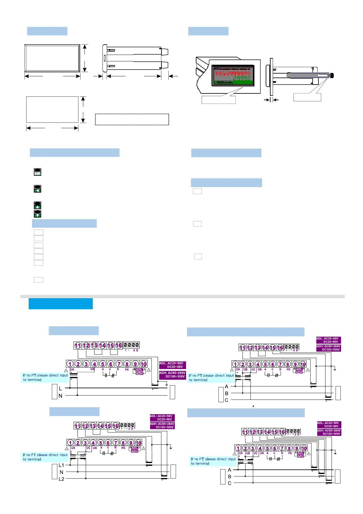
Installation
Dimension
This meter is installed does not exceed the maximum
operating temperature and humidity environment.
Output wiring
CL
BK
AK A L
BL
CK
Please check if the voltage is correct and connect to the right terminal number when wiring
CL
BK
AK
AL BL CK
CL
BK
AK
AL BL CK
CL
BK
AK
AL BL CK
2 24/
Unit: mm
S iz e 9 6 mm x 4 8 m m x 1 20 m m:
4 8. 0
Front
Cut size
4 4. 0
+ 0 . 2
9 2. 0
+ 0 . 2
9 6. 0 1 00 . 0
8 .0 1 2. 0
C u t si z e : 2 49 m m x 4 mm
+ 0 . 2 + 0 . 2
1.0 ~8.0 mm
FIX HOLDER:
104 mm(L ) / W M3
PANEL CUT-OUT:
92
+0.2
(W) x 44
+0. 2
(H) mm
ENT/
FN
?
R L
1
R L
2
EC
I 1
E C
I 2
k
w
h
M
K
k
w
W
?
W
H
1Phase 3 wire
Output
AO
RS485
Output
If no PT please direct input
to terminal
source
Relay output
Aux
Load
Output
AO
RS485
Output
If no PT please direct input
to terminal
Relay output
Aux
source
Load
If no PT please direct input
to terminal
Aux
Aux
Relay output
Output
AO
RS485
Output
If no PT please direct input
to terminal
source
Load
Output
AO
RS485
Output
3Phase 3wire 3CT (Unbalanced)
1Phase 2 wire
source
Load
3Phase 3wire 2CT (Unbalanced)
Relay output
With CLAMP CT, the secondary side do not ground or parallel connection, otherwise the meter burned■
With CLAMP CT, the secondary side do not ground or parallel connection, otherwise the meter burned■
E n d t e rm in al o hm
A89:;<= -1,/>?@!"ABC.DEBCAFG.1!
"3 )FGHIJKP4W.3
!"1 2 ),1-10~1-27LMNFGP W
!"1 ),1-14/1-1 ~ LMNFGP3W 6 27
!"3 ),1-1 1-1 /1-1 1- /P3W.1 3~ 5 7/1-18/ 20 1-21/1-23/1-24/1-
26/1-27LMNFG
!"3 ),1-1 1- /1- LMNFGP3W.2 7/ 20 23/1-26
!"3 ),1-1 1- /1- LMNFGP3W.3 7/ 20 23/1-26
!"3 ),1-1 1- /1-P4W.1 4~15/ 17~18 20~21/1-23~24/1-26~27
LMNFG
!"#$:1 p 2 w 1 p 3 w 3 p 3 w . 1 3 p 3 w . 2 3 p 3 w . 3/ / / / /
3 p 4 w . 1 3 p 4 w . 3/
!"#$%&:
v a v g. '()*+,-:
i a v g. '().+,-:
f r e q :
/012-
p . t l :'(340-
q . t l :'(3540-
s . t l :'(36740-
p f . a v g :'(+,408
$12-
v a : ()*-12A
vb :B()*-12
vc :C()*-12
ia :A().-12
ib :B().-12
ic :C().-12
p f - a :A(4012-
pf-b :B(4012-
pf-c :C(4012-
p - a :A(4012-
p-b :B(4012-
p-c :C(4012-
q - a :A(54012-
q-b :B(54012-
q-c :C(54012-
s - a :A(674012
s - b :B(674012
s - c :C(674012
RELAY / PULSE output of the outputs can
only choose a functional output
EX: Select PULSE output and then RELAY
function no output and vice versa
Clamp CT
Optional of Clamp CT, make sure
(1)CT of the SN number with the
CPM-10 SN number, as shown
( )2 On the label
A A Phase B B: - ; : -
Phase C C Phase; : - ;
According to the phase matching
Relay Pulse output
CL
BK
AK
AL
BL
CK
, ,%&'(CT) *+,-./0 123456
 Loading...