2 61187777G1-22A
This module has holes that are pre-drilled completely through the
module.
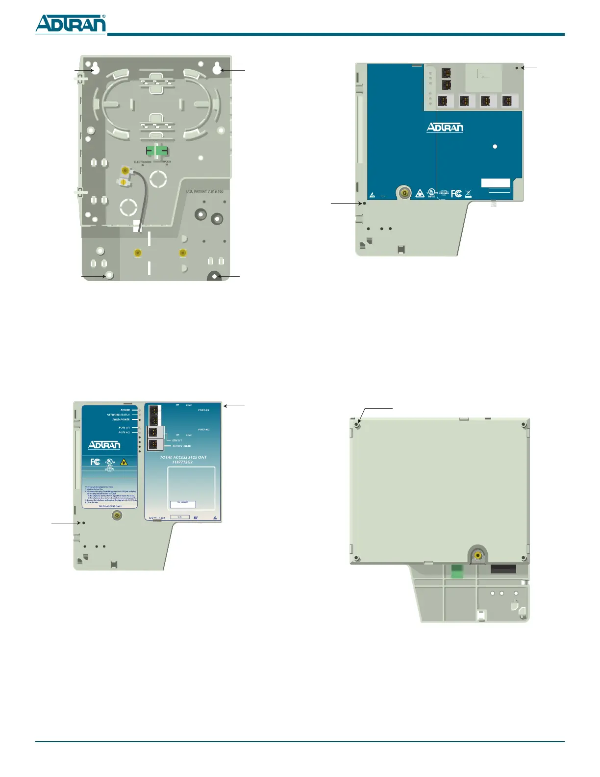
Before the 1st Generation Electronics Module can be secured, the
partially drilled hole must be completely drilled through the
housing. This is one of two holes that will be used to prevent the
Electronics Module from being opened.
Refer to the illustration below and complete the following
procedure:
1. On the reverse side of the Electronics Module there is a par-
tially drilled hole. Select an appropriate sized bit and com-
plete the hole by carefully drilling through the housing.
2. Remove any plastic shavings.
POTS 2
POTS 1
TELCO ACCESS
ETH 1 ETH 2
ETH 3
ETH 4
TOTAL ACCESS 354E
1287704G1
12V , 1.0A
POWER
NETWORK STATUS
TELEPHONE TROUBLESHOOTING
1. Identify the bad line.
2. Disconnect the plug from the appropriate POTS jack and plug
any working telephone into that jack.
If the telephone works, there is a problem inside the house.
If the telephone does not work, contact your service provider.
3. Remove the telephone and replace the plug into the POTS jack.
4. Close the unit.
CLEI
TEL. NUMBER
Pre-Drilled
Hole
Pre-Drilled
Hole
Partially Drilled Hole
4. Lock the ONT Mounting Bracket in place at the bottom with
the two remaining #6 Pan Head screws.
ELECTRONIC MODULES
There are two different type of Electronic Modules. The 1st
Generation Electronics Module is displayed below.
This module has one pre-drilled hole at the lower left hand side,
and one hole that is not completely drilled through at the top
right hand side.
The following is an illustration of the 2nd Generation electronics
Module.
Keyholes
Keyholes
#6 Pan Head
Screw
#6 Pan Head
Screw
FXS 0/1
FXS 0/2
Partially Drilled Hole
on Reverse
RING
TIP
RING
TIP
FXS 0/1
FXS 0/2
ETH 0/1
ETH 0/2
POTS 1
POTS 2
ETH 1
CLEI
TIP RING
TEL. NUMBER
TIP RING
TIP RING
TIP
RING
Pre-Drilled
Hole
 Loading...