+ All DIP Switches = On
GND
RS-485
BB-USOPTL4(-LS) or
BB-USPTL4(-LS)
NEG(-)
POS(+)
TDA(-)
TDB(+)
RDA(-)
RDB(+)
GND
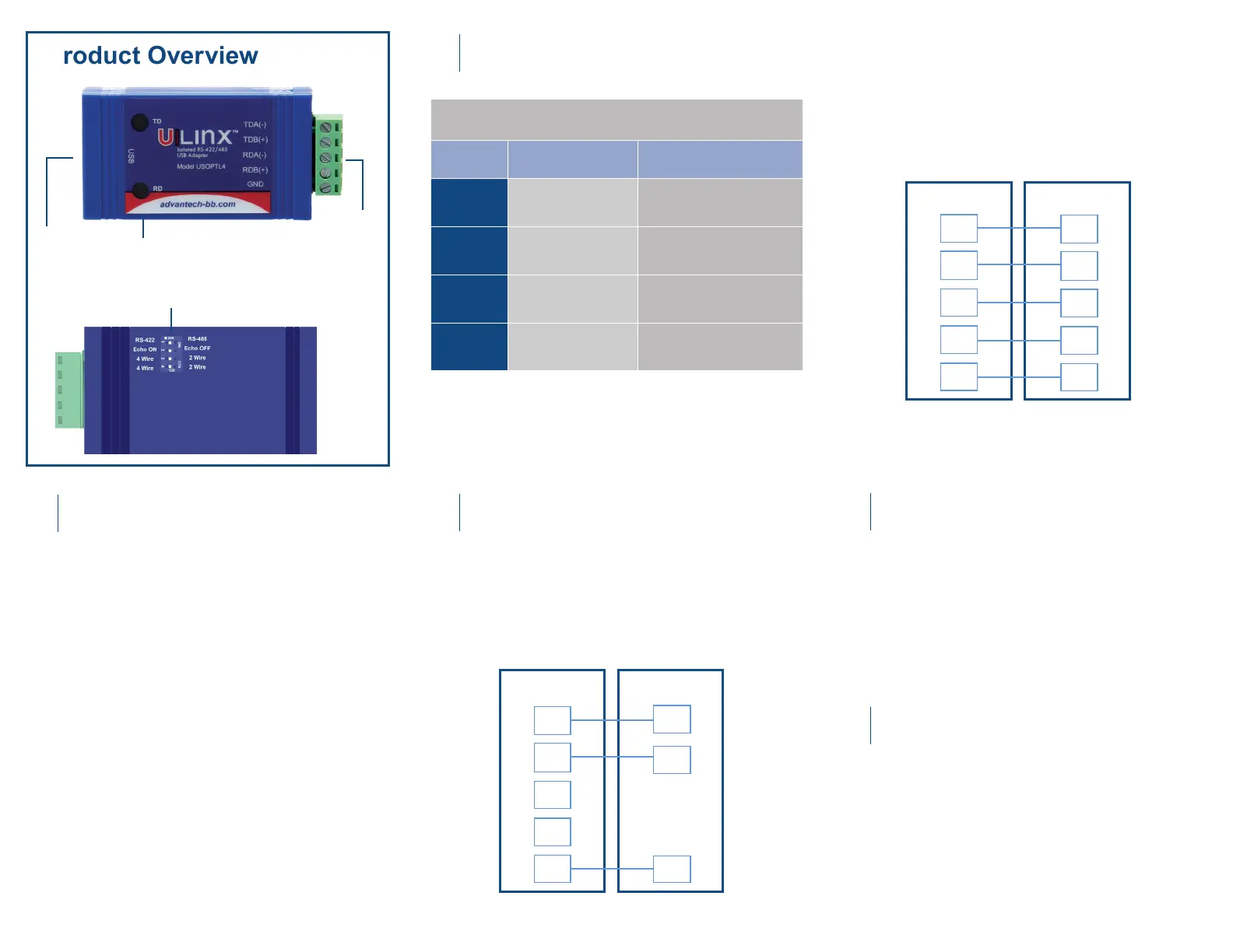
2 Wire Set-up
Product Overview
Use the included CD to install the converter’s
drivers.
After connecting the device, you can check
Device Manager to learn which COM port
number was assigned (Control Panel/
System/Hardware/Device Manager/Ports LPT
& COM).
You can re-assign COM numbers by clicking
the Advanced Settings button on the Port
Settings screen.
Warning: To prevent installation errors, do
not plug in the hardware until you have
already installed the drivers.
DIP SWITCH POSITION
Switch OFF (left) ON (right)
1
TD Always Enabled
(RS-422)
TD Only Enabled During Data
Transmission (RS-485)
2
RD Always Enabled
(ECHO On)
RD Disabled During Data
Transmission (ECHO Off)
3
4-Wire Mode 2-Wire Mode
4
4-Wire Mode 2-Wire Mode
• Set DIP switches 1, 3, 4 to ON.
• Set DIP switch 2 to OFF.
• Use HyperTerminal or another terminal program
to conrm passage of data through converter.
When everything is installed and connected,
the LEDs will blink to indicate that data trafc is
passing through the converter
Check LEDs
5
USB Port LED
Serial
Connecter
DIP Switches
2-Wire RS-485 (half-duplex)
+ RS-422 = All DIP Switches OFF
+ RS-485 = DIP 1 ON; DIP 2, 3 and 4 OFF
4-Wire RS-485 (full-duplex)
RS-422/485
TDA(-)
TDB(+)
RDA(-)
RDB(+)
GND
4 Wire Set-up
RDA(-)
RDB(+)
TDA(-)
TDB(+)
GND
Install Drivers
1
Set DIP Switches
2
Wire the Converter
3
Loopback Test (optional)
4
BB-USOPTL4(-LS) or
BB-USPTL4(-LS)
 Loading...