1) Predisposizione I∆n soglia d’ intervento
2) Selettore portata I∆n
x1 = 0,03...0,3A / x10 = 0,3...3A / x100 = 3...30A
3) Segnalazione apparecchio alimentato (LED verde)
4) Segnalazione intervenuto allarme (LED rosso acceso)
opp.interruzione collegamenti relé - toroide (LED rosso lampeggiante)
5) Pulsante di prova
6) Pulsante di ripristino
7) Selettore ripristino automatico - manuale
8) Selettore stato relé uscita: Nd (norm. diseccitato) -
Ne (norm. eccitato)
9) Predisposizione ritardo intervento
10) Indicazione istantanea della corrente differenziale (in %
del valore I∆n impostato)
PREDISPOSIZIONE
Operazioni da effettuare con apparecchio non alimentato.
☞ Rimuovere il frontale
☞ Predisporre la soglia di intervento, agendo sul selettore
di portata (2) e sul predispositore (1)
☞ Controllare che il valore di intervento selezionato sia
compatibile con la sensibilità minima rilevabile dal tra-
sformatore toroidale abbinato.
Toroide 28 I∆n minima = 0,03A
Toroide 35 e 80 I∆n minima = 0,03A
Toroide 110 I∆n minima = 0,1A
Toroide 140 I∆n minima = 0,3A
Toroide 210 I∆n minima = 0,3A
Toroide A110 I∆n minima = 0,5A
Toroide A150 I∆n minima = 0,5A
Toroide A300 I∆n minima = 1A
☞ Predisporre l'eventuale ritardo sull'intervento (9)
☞ Selezionare lo stato del relé d’uscita (8)
Impostare il tipo di ripristino (7): MANUALE = lo stato di
allarme permane fino a quando l’operatore non agisce sul
tasto RESET (6). AUTOMATICO = ad allarme intervenuto, l’apparec-
chio provvede automaticamente al ripristino, facendo tre tentativi
(1 ogni 60 secondi).Se dopo tre tentativi il dispositivo non si é ripristi-
nato, l’apparecchio entra in stato di allarme definitivo e deve essere
rispistinato manualmente (6).
N.B. Il rispristino é inibito con corrente differenziale persistente:
≅ 50% I∆n impostata
Verificare che il valore della tensione di alimentazione ausiliaria corri-
sponda a quello riportato in targa.
ISTRUZIONI DI CABLAGGIO
Rispettare scrupolosamente lo schema d'inserzione, una inesattezza
nei collegamenti è inevitabilmente causa di funzionamento
anomalo o di danni all'apparecchio.
L'ottenimento della piena funzionalità del sistema di protezione
differenziale è legato alle modalità di installazione, per cui si consi-
glia:
☞ Ridurre al minimo la distanza tra toroide e relè
☞ Utilizzare cavi schermati o intrecciati per la loro connessione
☞ Evitare di disporre i cavetti di connessione toroide-relé
parallelamente a conduttori di potenza. ➤
1) Setting intervention threshold I∆n
2) Range selector I∆n
x1 = 0,03...0,3A/ x10 = 0,3...3A/ x100 = 3...30A
3) Green LED for fed meter
4) Red LED for an occurred alarm or connection breakdown
between relay and ring current transformer (blinking red LED)
5) Test key
6) Reset key
7) Automatic-manual reset switch
8) Switch for state of output relay: Nd (normally de-energised)-
Ne (normally energised)
9) Setting intervention delay
10) Instantaneous display of earth leakage current (in % of
loaded I∆n value)
SETTING
Operations to be carried out with the relay off.
☞ Remove the front frame
☞ Setting the intervention threshold acting on range
selector (2) and on presetter (1)
☞ Check that selected intervention value is compatible with
the lowest sensitivity that can be detected from the
coupled ring current transformer.
28 ring CT lowest I∆n = 0,03A
35 or 80 ring CT lowest I∆n = 0,03A
110 ring CT lowest I∆n = 0,1A
140 ring CT lowest I∆n = 0,3A
210 ring CT lowest I∆n = 0,3A
A110 ring CT lowest I∆n = 0,5A
A150 ring CT lowest I∆n = 0,5A
A300 ring CT lowest I∆n = 1A
☞ Set the intervention delay (9)
☞ Select the state of output relay (8)
Set reset type (7): MANUAL = state of alert stays until the
operator presses RESET key (6). AUTOMATIC = when alarm
occurred, this instrument automatically resets, making three
attempts (1 every 60 seconds). If after three attempts the
device has not reset, the instruments turns into definitive
state of alert and must be manually reset (6).
N.B.: Reset is not possible with persistent residual current:
≅ 50% loaded I∆n.
Please check the value of auxiliary supply voltage corre-
sponds to the one shown on the label.
INSTRUCTIONS FOR WIRING
Please carefully follow the wiring diagram; an error in
connecting the relay may give rise to irregular working or
damages.
The achievement of differential protection system full
functionality is bound to the mounting way;therefore we
suggest:
☞ to reduce as much as possible the distance
between ring current transformer and relay
☞ to use only shielded or twisted cables for their connection
☞ to avoid in placing ring current transformer-relay
connection cables parallelly to power wires ➤
☞ Evitare di installare toroide e relè in prossimità di sorgenti di
campi elettromagnetici intensi (grossi trasformatori)
ISTRUZIONI DI MONTAGGIO
La posizione di fissaggio risulta completamente indifferente ai fini
del funzionamento.
☞ Binario 35mm EN50022: fissaggio a scatto. ■
☞ to avoid in mounting ring current transformer and relay
near sources of intense electromagnetic fields (big
transformers)
MOUNTING INSTRUCTIONS
Mounting position do not affect in any way the proper working.
☞ 35mm EN50022 rail DIN: snap-on mounting.■
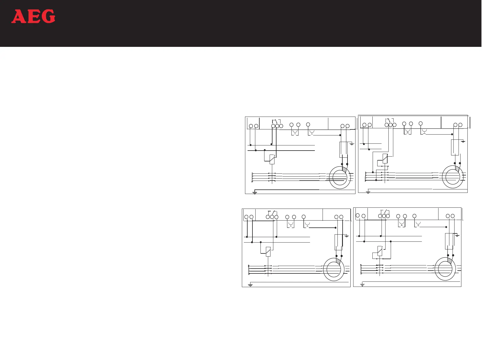
DESCRIZIONE FRONTALE FRONT DESCRIPTION SCHEMI D’INSERZIONE • WIRING DIAGRAMS
Posizione Contatti
In condizione di sorveglianza
(apparecchio alimentato)
Contact Position
In monitoring condition
(fed meter)
 Loading...