34
II
II
NN
NN
SS
SS
TT
TT
AA
AA
LL
LL
LL
LL
AA
AA
ZZ
ZZ
II
II
OO
OO
NN
NN
EE
EE
••
••
II
II
NN
NN
SS
SS
TT
TT
AA
AA
LL
LL
LL
LL
AA
AA
TT
TT
II
II
OO
OO
NN
NN
ROTAZIONE DEL GRUPPO VENTILANTE
Di serie le unità vengono fornite nella configurazione A di
fig. 9.
Su richiesta possono essere fornite anche nelle configura-
zioni B, C, D ed E.
La configurazione C può essere realizzata solo in fabbrica.
Le configurazioni D ed E prevedono i collegamenti frigorife-
ri all'interno della carpenteria.
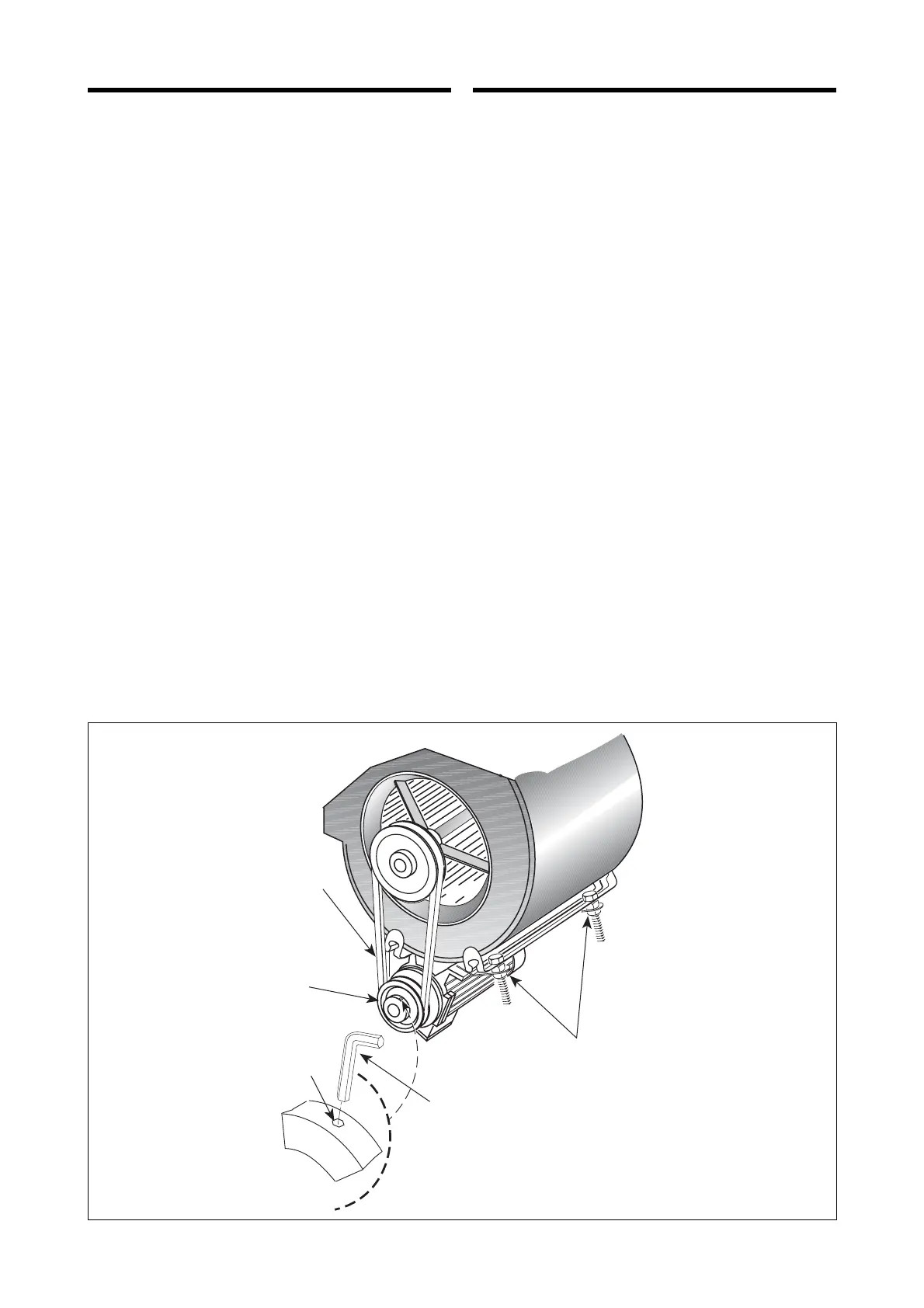
Per la rotazione del gruppo ventilante sul cantiere procede-
re come segue:
– togliere il pannello laterale (1) (fig. 10);
– togliere il pannello posteriore (2);
– smontare i tappi (3);
– togliere la cinghia di trasmissione (4);
– estrarre la puleggia (5);
– allentare le viti di fissaggio delle coclee dei ventilatori ed
estrarli dall'unità;
– ruotare i ventilatori come in fig. 11 e fissarli al telaio del-
l'unità con le viti precedentemente tolte;
– rimontare la puleggia (5);
– rimontare la cinghia (4) e regolarne la tensione;
– fissare i pannelli (2) ed (1);
– chiudere le bocche di mandata superiori (6) coi tappi (3).
ROTATION OF THE FAN GROUP
The units are supplied as standard in the configuration A
shown in fig. 9.
On request they may be also supplied in configurations B,
C, D, and E.
Configuration C can only be achieved in the factory.
Configurations D and E require refrigerant connections
within unit housings.
To rotate the fan group on site proceed as follows:
– remove side panel (1) (fig. 10);
– remove rear panel (2);
– remove covers (3);
– remove drive belt (4);
– remove pulley (5);
– remove the fan securing screws and remove the fans from
the unit;
– rotate the fans as shown in fig. 11 and secure them to the
frame using the screws removed previously;
– refit the pulley;
– refit the drive belt (4) and adjust the tension;
– replace panels (2) and (1);
– close the upward airflow outlets (6) with covers (3).