19
English
AGLLIJ 0907 - 4528550_03
INSTALLATION OF THE "GLL20" UNIT
- Open the packaging of the accessory,
flow frame and intake grid unit, remo-
ve the grid from the packaging and
check that it has not been damaged
during transport.
- Open the cover of the terminal board
on the electric box. Use a tool to relea-
se the pressurised hooks.
- Connect the power supply cables to
the terminal board as indicated in the
wiring diagram.
- Fix all cables using the cable gland.
- Close the cover of the electric terminal
board.
- Insert the electric box into the FCL unit
guide and make sure that the connec-
tors are well attached.
- The electric box must be fixed to the
FCL unit using two screws.
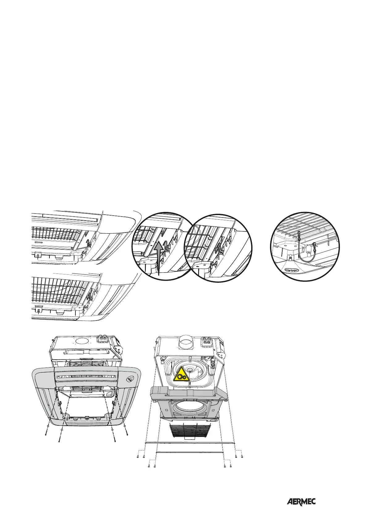
- Remove the intake grid by acting on
the 2 ratchets by ¼ of a turn.
- Hang the frame on the two support
hooks, pay attention to the assembly
position, the corner of the frame with
the AERMEC logo holder must coin-
cide with the corner of the FCL unit
electric box.
- ATTENTION: fix a safety cable snap
hook must then be attached to the
grid frame and the other snap hook to
the fan protection grid.
- Fix the frame to the unit using the 4
screws supplied.
CAUTION!! tighten the screws with
maximum coupling torque of 0.45
Nm. It is advised to use a screwdri-
ver, do not use non calibrated electric
screwdrivers. An excessive coupling
torque will damage the tray irrepara-
bly.
The frame guarantees sealing between
air intake and flow, therefore, it must
be fixed correctly to the unit without
undergoing deformations.
- Fix the intake grill to the safety cable.
- Mount the intake grid, hooking it to the
hinge on the frame.
- Close the intake grid and tighten the
two ratchets (on the side opposite the
hinge) by ¼ of a turn.
- Adjust the position of the unit by the
support bracket by means of the nuts,
in a way that the unit is level and the
frame rests slightly in the suspended
ceiling.
- Start the fan coil and carry out a fun-
ctioning test.
Electric box maintenance
If the electric box must be accessed for
maintenance, follow the indications
below:
- Open the filter grid (turn the two
ratchets by ¼ of a turn).
- Remove the lock screw on the corner
door with the Aermec logo.
- Remove the 2 lock screws from the
electric box.
- Slide the electric box downwards.
- Carry out the necessary maintenance.
- Re-mount everything performing the
disassembly procedure in reverse
order.
• Disassembly for maintenance
- Before performing any operation on
the unit, the electric power supply
must be interrupted.
- To access the inside of the unit,
remove the two cross-members fixed
to the frame with the screws. It is now
possible to remove the fan protection
grid and the polystyrene basin. (see
figure)
- DANGER!! Before re-applying voltage
to the unit, all components, especially
the protection grid, must have been
re-mounted correctly.
 Loading...