68
IFCLTY 1112 - 4528511_04
The hydraulic attachments are with flat stroke
fittings complete with supplied gaskets.
In the 4-pipe version of the unit, it is
mandatory to install the hot water coil
valve accessory. For this purpose use the
supplied gaskets, the accessory has gaskets
for connection to the system.
Information for the correct installation of
the valve is contained in the accessory's
instructions.
The flow and return pipes must be equal,
suitably dimensioned and insulated to
avoid heat dispersion and dripping during
functioning in cooling mode
The water, condensate drainage and electrical circuit ducts must be provided for.
CONNECTIONS
CONDENSATE DRAIN CONNECTIONS
During functioning in cooling mode the
internal unit removes humidity from
the air. The condensate water must
be eliminated by linking the proper
drainage pipe attachment with the
condensate system drain pipe.
In the "Module 600" unit, the
polystyrene basin has a hole that
allows to empty the condensate, useful
in the case of disassembly.
The draining hole must always be closed
again using the rubber cap.
The units are supplied as standard with
a number of floating pump-floats for
lifting the condensate from the basin to
the drainage consisting of one electric
card, one electric pump with non-
return valve and float with three-level
sensors: ON, OFF and Alarm.
The electrical supply to the pump-float
device must never be interrupted.
In the case of alarm the lifting device,
interrupts the flow of water in the coil.
The basin is fitted with an overflow hole
to ensure that the condensate water
runs off if the pump-float device is not
working. In this case dripping can be
seen from the grid.
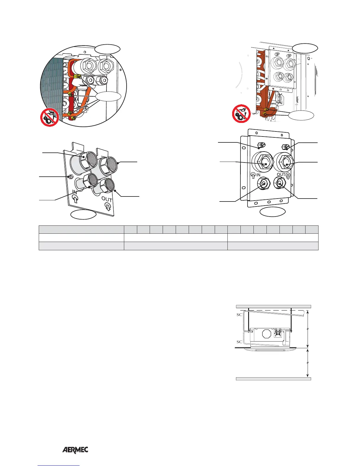
The pump allows a maximum head of
80 cm from the level of the suspended
ceiling. If this height is not sufficient
an aux. device must be used.
It is advised to use heat-insulated rigid
piping in order to avoid condensation
on the outer surfaces.
SC = Condensate drain (male Ø 16mm)
HYDRAULIC CONNECTIONS
1/50 ~ 1/100
MAX. 800mm
MAX. 3000mm
CONNECTIONS
(2) = Standard coil connections
Air = Standard coil air vent valve
(4) = Hot water coil connections
The unit can be connected to a fresh
air intake duct through the circular
flange accessory, applied to the vent.
The application of the flange requires
the opening of a hole on the side.
Connection to the outside is direct and
independent from unit ventilation.
The accessory also includes a deflector
to be mounted inside the unit.
CONNECTIONS FOR THE INTAKE OF EXTERNAL FRESH AIR
The unit can be connected to a pipe for
conditioned air flow into an adjacent
room, via the circular flange. The
application of the flange requires the
opening of a hole on the side.
CONNECTION FOR THE AIR FLOW CONDITIONED IN AN ADJOINING ROOM
(2) in
(4) out
(2) out
Air out
(4) in
600x600
Out
600x600
Out
840x840
(2) in
(4) out
(2) out
Air out
(4) in
Air out
840x840
Mod. FCL 32 36 42 62 72 82 102 122 34 38 44 64 84 104 124
Standard coil connections (2) ø 3/4”F 3/4”F
Additional coil connections (4) ø -- 1/2”F
 Loading...