Do you have a question about the AERMEC NRB 0800-3600 and is the answer not in the manual?
Controller with LCD, multilingual interface, and remote options for unit management.
Microchannel coils for high efficiency, reduced refrigerant, and optional corrosion resistance.
Benefits of electronic expansion valves for energy efficiency, especially at partial loads.
Details components of the refrigerant circuit, including compressors, coils, and heat exchangers.
Describes components of the hydraulic circuit, such as water filter and expansion vessel.
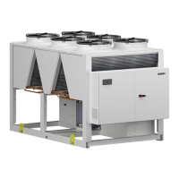
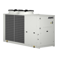
Covers the unit structure, outdoor installation aspects, and fan types.
Details safety devices like switches and transducers, and condensation control.
Details the hydraulic circuit without a hydronic kit, including components and water characteristics.
Describes the hydraulic circuit with pumps, including diagrams and water characteristics.
Details the hydraulic circuit with pumps and storage tank, including diagrams and water characteristics.
Explains the hydraulic circuit for units with a desuperheater, including diagrams and water characteristics.
Describes the hydraulic circuit for units with total recovery, including diagrams and water characteristics.
Presents the refrigerant layout for specific NRB models with valve configuration.
Shows the refrigerant layout for NRB units with desuperheater.
Illustrates the refrigerant layout for NRB units with total recovery.
Displays refrigerant layout for larger NRB models with optional valve configurations.
Shows refrigerant layout for NRB units with desuperheater and optional valve.
Illustrates refrigerant layout for NRB units with total recovery and optional valve.
Table showing compatibility of various accessories with different unit models and sizes.
Lists accessories that are factory-fitted, such as DCPX and DRE.
Discusses corrosion risks from salt in coastal environments and material protection.
Details atmospheric emissions and corrosive particles in industrial settings.
Explains the combined risks from salt and industrial emissions.
Covers pollution from vehicles and heating, and sulfur/nitrogen oxides.
Explains humidity and temperature as primary causes of corrosion, and lists corrosive gases.
Presents performance data for the NRB unit in standard configuration.
Details performance specifications for the NRB unit in 'L' version.
Shows performance data for the NRB unit in 'A' version.
Presents performance specifications for the NRB unit in 'E' version.
Details performance data for the NRB unit in 'U' version.
Shows performance data for the NRB unit in 'N' version.
Presents performance data for units with desuperheater.
Presents performance data for units with total recovery.
Shows SEER and seasonal efficiency for standard and inverter fans.
Details compressor type, regulation, number, circuits, and partialization.
Specifies refrigerant type (R410A) and load values for different versions.
Describes the system side heat exchanger type, number, and water flow rates.
Fan data for '0' version, including type, number, airflow, and power.
Fan data for 'J' version (inverter fans), including type, number, airflow, and power.
Weights for units with integrated hydronic kit type 00.
Weights for units with integrated hydronic kit type AA.
Illustrates minimum space requirements for single unit installations.
Minimum technical spaces for the 'L' version based on fan type and board configuration.
Minimum technical spaces for the 'U' version based on fan type and board configuration.
Minimum technical spaces for the 'N' version based on fan type and board configuration.
Discusses minimum distances for multiple unit installations.
Details operating limits (external air temp vs water produced) for the '0' version.
Operating limits for version 'L', including silenced/non-silenced modes.
Operating limits for versions A, E, U, N.
Operating limits for version 'A', including silenced/non-silenced modes.
Operating limits for version 'U', including silenced/non-silenced modes.
Operating limits for versions E and N, including silenced/non-silenced modes.
Operating limits for version 'E', including silenced/non-silenced modes.
Operating limits for version 'N', including silenced/non-silenced modes.
Pressure drops for the service side heat exchanger without hydronic kit.
Pressure drops for heat exchanger with filter, without hydronic kit.
Pressure drops for service side with PA-PJ/DA-DJ hydronic kit.
Pressure drops for service side with AA-AJ/BA-BJ hydronic kit.
Pressure drops calculation for the desuperheater.
Static pressure curves for pumps PAPI/AA÷AI.
Static pressure curves for pumps DADI/BA÷BI.
Explains the importance of minimum water content and provides calculation formulas.
Max system water content for various integrated hydronic kit types.
Factors for pressure drops based on average water temperatures.
Corrective factors for cooling capacity and input power due to fouling.
Correction factors for ethylene glycol in cooling and heating modes.
Correction factors for propylene glycol in cooling and heating modes.
Sound power and pressure level data for cooling mode.
Sound power levels for different versions and octave bands.
Sound pressure level measurements at 10 meters distance.
Sound pressure level measurements at 1 meter distance.