ACCEPTANCE TESTING
5-1-B-2
PULSE MODULATION
The following tests are for a 2030, 2031 or 2032 with the pulse modulation option fitted.
SPECIFICATION
Maximum input level: +5 V.
Minimum ON Level: +3.5 V.
Maximum OFF level: +1.0 V.
OFF/ON ratio : Greater than 70 dB at the carrier frequency.
Typically greater than 80 dB.
Additional output
level error : Less than 0.5 dB.
TEST EQUIPMENT
Description Minimum specification Example
Power meter ±0.1 dB from 30 kHz to 2.7 GHz. IFR 6960B
and 6912 sensor
Spectrum analyzer Frequencies up to 1.4 GHz. Capable of IFR 2386
measuring <-70 dBm.
Function generator DC capability. HP3325B
TEST PROCEDURES
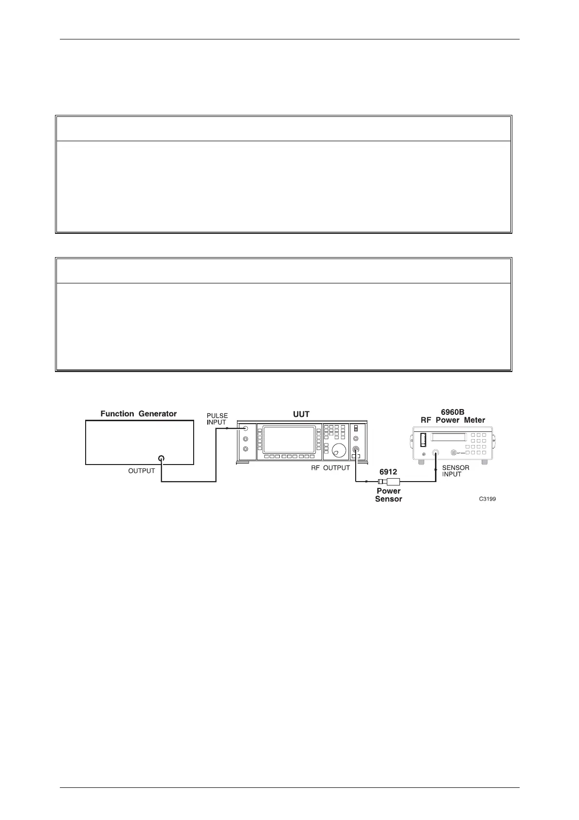
Fig. 5-1-B-1 Levels test set-up
Minimum 'ON' level
(1) Connect the test equipment as shown in Fig. 5-1-B-1.
(2) Set the UUT to [RF level] 0 dBm [Carrier freq.] 10 MHz and [Pulse Mod.].
(3) Set the function generator to give +3.5 V DC. The 0 dBm level should now
appear on the power meter.
Maximum 'OFF' level
(4) Set the function generator to give 1.0 V DC. The 0 dBm level should now
disappear from the power meter.

 Loading...