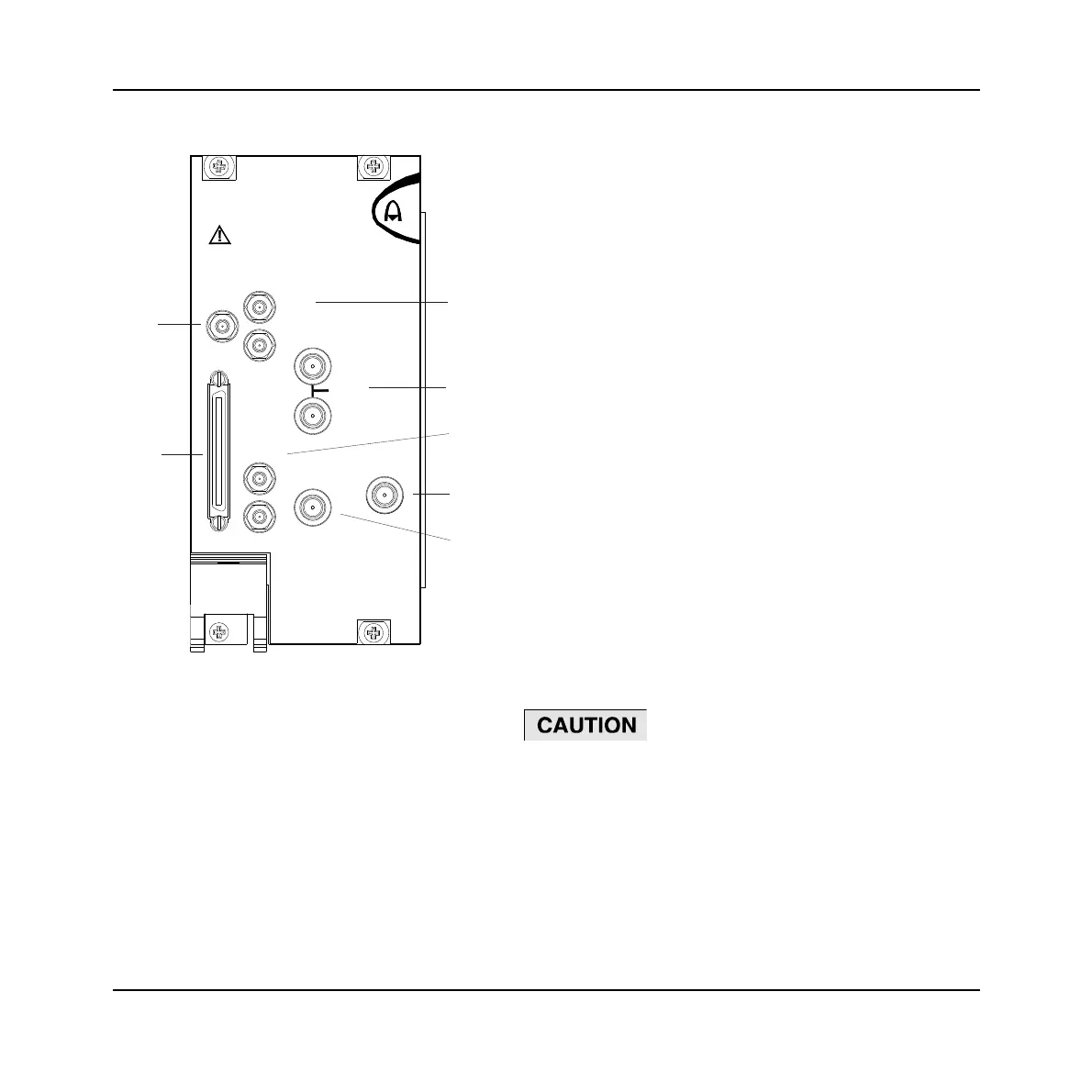
FRONT-PANEL CONNECTORS
18
1 I+ , I− , I IN
Option 01
only
Analog I output (I+ and I−), 50Ω single-
ended, 100 Ω differential. SMB sockets.
Analog I input (I IN), selectable
50Ω/100 kΩ.
2 10 MHz I/O Two SMA I/O sockets in parallel.
Input
External frequency standard input for
sampling clock. 0.4 to 4 V pk-pk into 50 Ω.
Output
Link-through from input.
3 Q+ , Q− ,
Q IN
Option 01
only.
Analog Q output (Q+ and Q−), 50Ω single-
ended, 100 Ω differential. SMB sockets,
50 Ω.
Analog Q input (Q IN), selectable
50Ω/100 kΩ.
4 RF OUT
SMA socket, 50 Ω.
5 LO IN 1.5 to 3 GHz, nominally 0 dBm. SMA
socket, 50 Ω.
6 DATA 68-way VHDCI connector for LVDS data
I/O, 14-bit IQ digital data input.
See Appendix B for details.
7
TRIG Input, TTL +ve or –ve edge. SMB socket,
50 Ω.
C6346
REV
PWR
25dBm MAX
TRIG
I+ I IN
I-
10 MHz
I/O
DATA
Q+ Q IN
LO IN
Q-
RF OUT
1
2
3
4
5
6
7
Fig. 3 3021C/3026C front panel
Maximum safe power
Reverse power handling: not to exceed +25 dBm
Artisan Technology Group - Quality Instrumentation ... Guaranteed | (888) 88-SOURCE | www.artisantg.com
 Loading...