MAKE SURE THAT ELECTRIC
MOTORS ARE SWITCHED OFF
BEFORE STARTING ANY
MAINTENANCE SERVICE.
Motors must be protected against acci-
dental starts.
When performing any maintenance
service, disconnect the motor from the power
supply. Make sure all accessories have been
switched off and disconnected.
In order to prevent from penetrating dust
and/or water into the terminal box, cable glands
or threaded pipe in the lead holes must be
installed.
Do not change the regulation of the
protecting devices to avoid damaging.
2 - Operating Conditions
Electric motors, in general, are designed
for operation at an altitude of 1000m above sea
level for an ambient temperature between 0ºC
and 40ºC. Any variation is stated on the
nameplate.
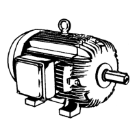
COMPARE THE CURRENT, VOLTAGE,
FREQUENCY, SPEED, OUTPUT AND
OTHER VALUES DEMANDED BY THE
APPLICATION WITH THE DATA GIVEN
ON THE NAMEPLATE.
Motors supplied for hazardous locations
must be installed in areas that comply with that
specified on the motor nameplate.
KEEP AIR INLET AND OUTLET FREE
AND CLEAN. THE AIR BLOWN OUT
BY THE MOTOR SHALL NOT ENTER
AGAIN. THE DISTANCE BETWEEN
THE AIR INLET AND THE WALL
MUST BE AROUND ¼ OF THE
INLET OPENING DIAMETER.
3 - Foundation
Motors provided with feet must be installed
on solid foundations to avoid excessive
vibrations.
The purchaser is fully responsible for the
foundation.
Metal parts must be painted to avoid
corrosion.
The foundation must be uniform and suf-
ficiently tough to support any schock. It must be
WEG MOTORS ARE DYNAMICALLY
BALANCED WITH HALF KEY, AT NO
LOAD AND UNCOUPLED.
Transmission elements such as pulleys,
couplings, etc must be dynamically balanced
with half key before installation.
Use always appropriate tools for installation and
removal.
6 - Alignment
ALIGN THE SHAFT ENDS AND
USE FLEXIBLE COUPLING,
WHENEVER POSSIBLE.
Ensure that the motor mounting devices
do not allow modifications on the alignment and
further damages to the bearings.
When assembling a half-coupling, be sure
to use suitable equipment and tools to protect
the bearings.
Suitable assembly of half-coupling:
Check that clearance Y is less than
0.05 mm and that the difference X1
to X2
is less
than 0.05 mm, as well.
Note: Dimension X1 and X2 must be
3mm minimum
Figure and alignment tolerances
designed in such a way to stop any vibration
originated from resonance.
4 - Drain Holes
Make sure the drains are placed in the
lower part of the motor when the mounting
configuration differs from that specified on the
motor purchase order.
5 - Balancing
7 - Belt Drive
When using pulley or belt coupling, the
following must be observed:
Belts must be tighten just enough to avoid
slippage when running, according to the
 Loading...