8
Testing Multimode or Single-mode Links
Step I - Set the Reference (One Jumper Method)
Turn on the OPM and OLS. Allow OLS to stabilize (minimum of 2 minutes).1.
If not using WAVE ID feature, set both instruments to the desired wavelength.2.
Select transmit and receive jumpers (fiber type must match link to be tested).3.
MM:4. Wrap and secure transmit jumper five times around mandrel.
SM (TIA testing only): Make and secure 30mm loop in a transmit jumper.
Clean both ends of the transmit jumper!
Connect the transmit jumper to the OLS output port (MM or SM respectively). 5.
Mount adapter cap on the OPM (must match free connector on transmit jumper). 6.
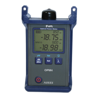
Connect transmit jumper (free end) to the OPM. Display optical power in [dBm].7.
If measured power is outside of the normal range (specified by manufacturer), 8.
clean all fiber connections or replace the transmit jumper. Repeat steps 4 - 7.
Set reference level: on OPM, press and hold [Ref/Set] until [HELD SET] is 9.
displayed to store currently measured level as the new reference level. Once set,
OPM switches to [dB] mode. OPM should display [0 dB] ± 0.05 dB.
OLS
OPM
0 dB
Transmit jumper
Mandrel wrap - MM (shown),
or 30 mm loop - SM
4
5
7
6
 Loading...