EasyManua.ls Logo

Agora Models Bismarck - User Manual

Agora Models Bismarck
56 pages
Print Icon
To Next Page IconTo Next Page
Loading...
Pack 11
|
Build Instructions
Your 1:200 scale model of the legendary battleship Bismarck is packed with
intricate details which precisely replicate every aspect of this state-of-the-
art warship. Each piece has been created using premium quality materials to
bring maximum enjoyment during your complete build.
In your eleventh model pack, you will assemble:
© 2020 Hachette Partworks Ltd.
North America Edition by Agora Models
STAGE 117: ROTATION MOTOR FOR THE
THIRD 38CM GUN TURRET
STAGE 118: FITTING THE STERN
STAGE 119: THE AFT CIRCUIT BOARD
STAGE 120: THE TWO OUTER PROPELLERS
STAGE 121: THE CENTRAL PROPELLER
STAGE 122: THE GEARBOX FOR THE
PROPELLERS
STAGE 123: THE TWIN RUDDERS
STAGE 124: THE AFT ANCHOR AND MOTOR
STAGE 125: MAINMAST AND FOUR AA GUNS
STAGE 126: THE EIGHTH UPPER DECK SECTION
STAGE 127: LAST SECTION OF THE UPPER DECK
STAGE 128: THE FOURTH 38CM GUN TURRET
Question and Answer IconNeed help?

Do you have a question about the Agora Models Bismarck and is the answer not in the manual?

Overview

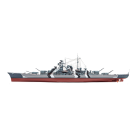
This document outlines the assembly instructions for Pack 11 of the 1:200 scale model of the legendary battleship Bismarck. This pack focuses on adding intricate details and functional components to the model, ensuring a precise replication of the original warship. The build process is divided into several stages, each addressing a specific part of the ship.

Stage 117: Rotation Motor for the Third 38cm Gun Turret

This stage involves fitting the rotation motor for the third 38cm gun turret.

  • Function Description: The motor (117-01) is responsible for rotating the third 38cm gun turret. It works in conjunction with a cog (117-02) that interlocks with the existing cog (112-09) on the aft superstructure.
  • Technical Specifications:
    • Motor: 117-01 (24BYJ48 6VDC Step Motor)
    • Cog: 117-02
    • Cable label: 117-03 (C-6)
    • Screws: Three 2.3 x 5mm PWB screws
  • Usage Features: The motor is fitted to the underside of the deck of the aft superstructure, ensuring the cog teeth interlock for smooth rotation.
  • Maintenance Features: The instructions emphasize careful handling to avoid damaging protruding gun barrels during installation.

Stage 118: Fitting the Stern

This stage focuses on completing the hull by fitting the stern section.

  • Function Description: This stage involves attaching the stern (118-01) and its port (118-02) and starboard (118-03) connectors to the keel section (115-01) and hull section (116-02), completing the aft part of the hull.
  • Technical Specifications:
    • Stern: 118-01
    • Port connector (L): 118-02
    • Starboard connector (R): 118-03
    • Screws: Six 2 x 4mm PM screws
  • Usage Features: The stern is secured using multiple screws, with careful alignment of screw holes to ensure a flush fit.
  • Maintenance Features: The instructions advise placing the model on a worktop to access the stern end of the hull and ensure proper alignment.

Stage 119: The Aft Circuit Board

This stage is a preparatory stage with no assembly work.

  • Function Description: The aft circuit board (119-01) is a key electronic component that will be fitted beneath the aft superstructure in a later stage. It serves as a central hub for various electronic connections.
  • Technical Specifications:
    • Circuit board: 119-01
  • Usage Features: This stage primarily involves identifying and preparing the circuit board for future installation.
  • Maintenance Features: No specific maintenance is required at this stage, as it's a "take a break" stage.

Stage 120: The Two Outer Propellers

This stage involves arranging and connecting cables for the propellers.

  • Function Description: This stage focuses on preparing the cabling for the two outer propellers, which will be fitted in a subsequent stage. It involves running cables from the 38cm turret motor through a bracket in the upper deck structure.
  • Technical Specifications:
    • Port propeller with bracket, shaft, support and sleeve: 120-01
    • Starboard propeller with bracket, shaft, support and sleeve: 120-02
    • Two brackets and a shaft grip: 120-03
    • Screws: Nine 2 x 4mm PM screws, Three 2 x 3mm PM screws, Five 2 x 6mm PB screws (only 2 x 6mm PB screws are used in this stage)
  • Usage Features: The aft superstructure section (64-01 and 99-01) is placed in support brackets to allow access to the underside of the upper deck.
  • Maintenance Features: Care is advised to avoid damaging existing parts during cable arrangement.

Stage 121: The Central Propeller

This stage involves fitting the two outer propellers and the central propeller.

  • Function Description: This stage involves fitting the port (120-01) and starboard (120-02) propellers, and the central propeller (121-02), to the hull. It also includes attaching the motor for the propellers (121-01) and its cable label (121-03).
  • Technical Specifications:
    • Motor for the propellers: 121-01
    • Central propeller with shaft, support and sleeve: 121-02
    • Cable label (D-2): 121-03
    • Screws: Four 2 x 4mm PM screws, Two 2 x 3mm PM screws (not used in this stage)
  • Usage Features: The propellers are fitted by threading their shafts through openings in the keel section (111-01) and securing them with screws and superglue.
  • Maintenance Features: Spare screws from Stage 120 are to be stored safely for later use.

Stage 122: The Gearbox for the Propellers

This stage involves assembling the gearbox and fitting the cog shafts.

  • Function Description: This stage involves assembling the gearbox for the propellers, which connects the propeller motor to the propeller shafts. It includes fitting various cogs, pivot pins, and cog shafts into the gearbox housing.
  • Technical Specifications:
    • Port gearbox support: 122-01
    • Starboard gearbox support: 122-02
    • Upper part of the gearbox: 122-03
    • Lower part of the gearbox: 122-04
    • Three cogs: 122-05
    • Cog: 122-06
    • Cog: 122-07
    • Cog: 122-08
    • Three small cogs: 122-09
    • Port cog and pin housing: 122-10
    • Starboard cog and pin housing: 122-11
    • Three pivot pins: 122-12
    • Three grips and a bracket: 122-13
    • Two cog shafts: 122-14
    • Cog shaft: 122-15
    • Two cog shafts: 122-16
    • Cog shaft: 122-17
    • Screws: Thirteen 2 x 4mm PM screws, Four 2 x 3mm PM screws, Nine 2 x 4mm PB screws, Seven 2 x 6mm PB screws
  • Usage Features: The gearbox components are carefully fitted and secured with screws, ensuring that the cogs mesh correctly and the shafts rotate freely.
  • Maintenance Features: After fitting, it's important to check that the propellers can rotate freely.

Stage 123: The Twin Rudders

This stage involves assembling the rudders and fitting the motor.

  • Function Description: This stage involves assembling and fitting the twin rudders (123-06) and their motor (123-01) to the stern of the model. It includes attaching cogs (123-03, 123-04) and a cog support (123-05) to ensure proper rudder movement.
  • Technical Specifications:
    • Motor for the rudders: 123-01
    • Large cog: 123-02
    • Port cog (L): 123-03
    • Starboard cog (R): 123-04
    • Cog support: 123-05
    • Two rudders: 123-06
    • Cable label (D1): 123-07
    • Screws: Five 2 x 4mm PWM screws
  • Usage Features: The rudders are positioned so that their teeth point towards the center of the hull, ensuring parallel movement. The motor is fixed in place, with its cog interlocking with the rudder cogs.
  • Maintenance Features: The instructions note that the motor fit might be a bit wobbly, which will be fixed in a later stage.

Stage 124: The Aft Anchor and Motor

This stage involves assembling the gearbox for the aft anchor and fitting the anchor.

  • Function Description: This stage involves assembling the gearbox for the aft anchor and fitting the anchor (124-10/124-11) to the hull. It includes attaching the anchor motor (124-01), anchor chain (124-09), and various cogs and shafts within the gearbox housing.
  • Technical Specifications:
    • Anchor motor: 124-01
    • Gear housing (left side): 124-02
    • Gear housing (right side): 124-03
    • Cog with brake tab: 124-04
    • Cog with cable reel: 124-05
    • Cable reel: 124-06
    • Cog on shaft: 124-07
    • Worm gear on shaft: 124-08
    • Anchor chain: 124-09
    • Anchor shank: 124-10
    • Anchor head: 124-11
    • Anchor ring: 124-12
    • Shaft (shorter): 124-13
    • Shaft (longer): 124-14
    • Switch and cable: 124-15
    • Cable label (D-7): 124-16
    • Cable label (D-8): 124-17
    • Screws: Three 2 x 4mm PM screws, Four 1.7 x 6mm PB screws
  • Usage Features: The anchor chain is threaded through a hole in the stern, and the gearbox is positioned to allow the anchor to be raised and lowered.
  • Maintenance Features: Superglue is used to secure certain components, and careful alignment is emphasized for proper function.

Stage 125: Mainmast and Four AA Guns

This stage involves assembling the mainmast and four AA guns.

  • Function Description: This stage involves assembling the mainmast, including its upper (125-03), middle (125-02), and lower (125-01) sections, along with various ladders (125-09), railings (125-10), and antenna (125-12). It also includes assembling and fitting four twin AA guns (125-05, 125-06, 125-07) to the aft superstructure.
  • Technical Specifications:
    • Mainmast (lower section): 125-01
    • Middle section of the mainmast (E to I): 125-02
    • Upper section of the mainmast (A to D): 125-03
    • Two vents and an antenna (J to L): 125-04
    • Four heavy AA gun mounts: 125-05
    • Four twin barrels of the AA guns: 125-06
    • Four bases for the AA guns: 125-07
    • Metal parts (1 to 6): 125-08
    • Four ladders (7 to 10): 125-09
    • Railing: 125-10
    • Spar support: 125-11
    • Antenna: 125-12
  • Usage Features: The mainmast sections are glued together, and ladders are bent and fitted. The AA guns are assembled with barrels and base plates, then pressed into holes on the superstructure deck without glue to allow rotation.
  • Maintenance Features: Superglue is used for securing various parts of the mainmast. The AA guns are designed to rotate, so no glue should be used for their final placement.

Stage 126: The Eighth Upper Deck Section

This stage involves adding details to the upper deck section and fitting railings.

  • Function Description: This stage involves adding various details to the eighth upper deck section (126-01), including skylights (126-03), loading practice machines (126-03), smoke generation containers (126-04), and depth charges (126-04). It also includes fitting six railings (126-05, 126-06, 126-07, 126-08) around the aft superstructure.
  • Technical Specifications:
    • Eighth upper deck section: 126-01
    • Skylights and two loading practice machines: 126-03
    • Eleven smoke generation containers and ten depth charges: 126-04
    • Two railings: 126-05
    • Two railings: 126-06
    • Railing (port): 126-07
    • Railing (starboard): 126-08
  • Usage Features: Skylights, machines, containers, and depth charges are glued into recesses on the deck. Railings are bent along fold lines and glued into holes on the deck covering (102-01) and superstructure deck (102-02).
  • Maintenance Features: The instructions note that an AA gun shown in some photos will be supplied in a later pack.

Stage 127: Last Section of the Upper Deck

This stage involves adding details to the aft upper deck section.

  • Function Description: This stage involves adding details to the aft upper deck section (127-01), including skylights (127-02, 127-03), an anchor chain opening (127-04), chain holder (127-04), depth charges (127-04), electric capstans (127-05), depth charge racks (127-06), platforms with railing (127-07), and ladders (127-08). It also involves connecting the eighth upper deck section (126-01) with the aft upper deck section (127-01).
  • Technical Specifications:
    • Aft upper deck section: 127-01
    • Details for the aft deck (A to D): 127-02
    • Skylights: 127-03
    • Anchor chain opening, chain holder and depth charges (E to H): 127-04
    • Two electric capstans (I to L): 127-05
    • Two depth charge racks (M, N): 127-06
    • Two platforms with railing (O, P): 127-07
    • Four ladders (Q to S): 127-08
    • Screws: Five 2.3 x 4mm PB screws
  • Usage Features: Skylights, anchor chain opening, chain holder, depth charges, capstans, depth charge racks, platforms, and ladders are glued into their respective positions. The two deck sections are fixed together with screws.
  • Maintenance Features: Ladders are bent to create mirror images, and careful alignment is crucial for proper fit.

Stage 128: The Fourth 38cm Gun Turret

This stage involves assembling the gun turret and fitting the barbette.

  • Function Description: This stage involves assembling the fourth 38cm gun turret, including its housing (128-03), base (128-04), gun barrels (128-15), periscopes (128-08), clutch shaft (128-10), and motor (128-01). It also includes fitting the barbette (128-02) into the upper deck.
  • Technical Specifications:
    • Motor: 128-01
    • Barbette: 128-02
    • Gun turret housing: 128-03
    • Base of the turret: 128-04
    • Connector for barrels: 128-05
    • Tension spring: 128-06
    • Motor mounting (upper part): 128-07
    • Two periscopes: 128-08
    • Twin barrel cradle with base plate: 128-09
    • Clutch shaft: 128-10
    • Motor mounting (lower part): 128-11
    • Left side rangefinder arm hood: 128-12
    • Right side rangefinder arm hood: 128-13
    • Ring: 128-14
    • Two gun barrels: 128-15
    • Two ladders: 128-16
    • Two washers: 128-17
    • Cable label: 128-18
    • Screws: Eleven 2 x 6mm PB screws
  • Usage Features: Gun barrels are fitted through holes in the housing, and periscopes, ladders, and rangefinder hoods are glued in place. The motor and its mounting are assembled, and the barbette is fitted into the upper deck.
  • Maintenance Features: Superglue is used for securing periscopes, ladders, and rangefinder hoods. Two washers (128-17) are inserted to provide a better fit for the rudder motor. The instructions note that two AA guns shown in some photos will be fitted in a future stage.

Agora Models Bismarck Specifications

General IconGeneral
BrandAgora Models
ModelBismarck
CategoryToy
LanguageEnglish

Related product manuals