Do you have a question about the Agri-Fab 45-0545 and is the answer not in the manual?
Provides essential safety rules for operating the spiker/spreader, including manual review and operator conduct.
Explains the meaning of the 'Attention!!' symbol used to highlight safety precautions.
Lists and labels all individual parts provided in the product's packaging for assembly.
Illustrates and labels hardware components at their actual size for easy identification during assembly.
Illustrates and labels hardware components not shown at their actual size.
Comprehensive list of all parts with corresponding part numbers, quantities, and descriptions.
Specifies necessary assembly tools and emphasizes caution with sharp spike disks.
Guides pressing bearings into spike disks and drive disks prior to axle assembly.
Instructs on pressing bearings into both ends of the center braces for proper function.
Details the assembly of a 1/2" spacer and a 5/8" washer onto the main axle.
Describes inserting the axle through the spreader frame, aligning with the pre-assembled sprocket.
Guides mounting drive disks, spike disks, and various spacers onto the axle in sequence.
Crucial reminder to ensure spike disks are oriented correctly as shown in assembly diagrams.
Details attaching center braces and a 3.2" spacer onto the axle, ensuring correct brace orientation.
Guides mounting additional spike disks and a spring onto the axle for proper operation.
Details the assembly of the final two spike disks and a 2.9" spacer onto the axle.
Explains using plastic ties to compress springs for easier assembly of remaining parts onto the axle.
Details assembling a 2.9" spacer, two spike disks, and a 5/8" washer onto the axle.
Guides sliding the axle through the frame and securing it with a cotter pin and washer.
Instructs on securing drive disks with cotter pins and removing plastic ties.
Details assembling the drive chain around the sprockets using a connecting link.
Guides the temporary installation of carriage bolts for the lift tube assembly, advising not to tighten.
Details attaching the lift tube assembly to the spreader using shoulder bolts and lock nuts.
Guides attaching the tongue and braces to the hopper and frame assembly, advising not to tighten.
Details assembling the plastic grip, flow control arm, and flow control rod with washers and nuts.
Guides attaching the hopper brace and hitch bracket to the tongue and hopper assembly.
Details assembling the tongue braces and finally tightening all previously assembled bolts and nuts.
Guides assembling the wheels onto the transport tube using bolts, washers, and nuts.
Details attaching the flow control gauge to the hopper brace using a carriage bolt, washer, and knob.
Details adjusting the ferrules on the control rod for proper exposed thread length.
Provides steps to check and adjust hopper flow plates for complete opening and closing.
Guides checking and adjusting tension on the flow control arm and nuts for proper plate tension.
Details attaching the transport handle and its grip to the lift assembly arm.
Guides attaching the chain cover and installing the hitch pin and hair cotter pin.
Provides step-by-step instructions for operating the spiker/spreader, including setting and application.
Offers a chart with recommended flow rate settings for different materials at a specific towing speed.
Offers practical tips for achieving uniform application, overlap, and avoiding lawn damage.
Reiterates the warning about sharp spike points and exercising caution when working near them.
Outlines checks for tightness, emptying hopper, and washing/drying after each use.
Advises applying oil to metal parts, wheels, bearings, and drive chain annually.
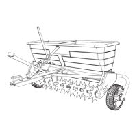
A diagram illustrating the spiker/spreader with numbered parts corresponding to the parts list.
Lists parts with their reference numbers, part numbers, quantities, and descriptions.
An exploded view of the entire spiker/spreader showing how all components fit together.
Continues the detailed list of parts with their reference numbers, part numbers, quantities, and descriptions.
Provides contact information and website for ordering replacement parts from SpeedEPart.
| Model Number | 45-0545 |
|---|---|
| Material | Steel |
| Hitch Type | Tow-Behind |
| Adjustable Height | No |
| Color | Black |
| Product Type | Aerator |