Do you have a question about the Agrident ASR650 and is the answer not in the manual?
Explanation of terms and abbreviations used in the manual.
Explanation of how RFID technology operates with transponders and readers.
Details on supported transponder types like FDX-B and HDX.
Key guidelines for optimizing reading performance with the ASR650.
How metal proximity affects antenna performance and tuning.
Instructions and best practices for physically mounting the antenna.
Wiring details for connecting the antenna to the reader's ST7 connector.
Explanation of antenna field distribution and optimal tag orientation.
Specifies minimum antenna impedance requirements based on transmit power.
Examples and rules for antenna placement near metal bars to minimize losses.
Technical specifications including power, frequency, range, and interfaces.
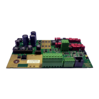
Visual guide and instructions for connecting the ASR650 reader board.
Detailed pinout and function of the ST2 connector for power and communication.
Pin assignment for connecting the antenna to the reader via ST7.
Details on connecting an external LED board and its functionality.
Information on connecting antenna multiplexers via the ST3 connector.
Explanation of the on-board LEDs indicating reader status and operating conditions.
Guidelines for selecting and connecting appropriate DC power supplies.
Details on using the RS232 interface for communication with the reader.
Information on the RS485 interface for multipoint communication.
Instructions for installing the ASR-PC-Demo software.
Steps to launch and connect to the ASR650 using the demo software.
Overview of the 'File' menu options within the ASR-PC-Demo software.
Details on the 'Quit' option within the 'File' menu.
Explanation of the 'Settings' menu and its sub-items for reader configuration.
How to establish and configure serial or TCP/IP connections in the software.
Functionality for scanning available ports to find compatible devices.
Options for enabling and configuring log file creation for tag read data.
How to select the correct reader model within the software.
Enabling or disabling audible alerts for tag reads.
Creating, saving, and loading reader configuration files.
Overview of diagnostic and utility tools available in the software.
Using the monitor to view and analyze serial communication data.
Functionality for counting and logging read transponders, similar to log files.
Performing automated diagnosis for antenna tuning and noise levels.
Accessing software information and firmware update tools.
Detailed breakdown of the ASR-PC-Demo main interface elements.
Display area for received transponder IDs and associated data.
Buttons for reading, applying, and resetting reader settings.
Status indicators for the reader's connection to the software.
Area for displaying status messages and operation progress.
Tab displaying a list of all transponders read since connection.
Configuration of common operating characteristics like serial number and transponder types.
Requesting the reader's serial number and firmware version.
Enabling or disabling support for different transponder technologies.
Setting the reader's operating mode (Continuous, Requested, Trigger).
Assigning unique network addresses for readers on an RS485 bus.
Configuring RF-field timing patterns for FDX and HDX transponders.
Checking reader voltages (V_in, V_rf, V_antenna) for operational status.
Setting the baud rate for RS232 and RS485 communication interfaces.
Defining priority between tag reading and communication tasks.
Configuring output for zero tag reads or HDX headers.
Accessing antenna tuning information and configuration options.
Enabling or disabling the automatic tuning procedure upon reader startup.
Allowing automatic adjustment of tuning values based on environmental changes.
Displaying key antenna status values like voltage, phase, CP, and impedance.
Requesting and viewing the antenna tuning curve.
Manually starting the autotuning process with options for LED feedback.
Settings related to the transmitter and receiver functions.
Manually switching the RF field on or off for specific applications.
Selecting the transmitter output power level.
Adjusting receiver sensitivity for FDX and HDX technologies.
Configuring how transponder data is formatted for output.
Overview of available output formats and their characteristics.
Steps to select and configure different output data formats.
Detailed explanation of output formats like Custom, ISO 24631, NLIS.
Creating custom output strings by selecting individual data fields.
Configuration settings for Data Block Flag, Antenna Number, Extended Code, Country Code, Delimiters, etc.
Details on the ISO 24631 output format, including telegram structure.
Explanation of the NLIS output format, similar to Short ASCII 15 with a space delimiter.
Format for transmitting 15 digits (country code + national ID) in ASCII.
Format for transmitting 16 digits, including the leading zero of the country code.
Transmitting only the last 10 digits of the national identification code.
Mechanisms for synchronizing multiple readers operating in close proximity.
Selecting synchronization modes (No Sync, Wireless, Wired).
Using wireless signals for synchronizing multiple readers.
Using cables for reliable synchronization between readers.
Configuring a reader to only sync as a slave, not a master.
Triggering sync based on specific sync pulses.
Evaluating RSSI levels to determine synchronization readiness.
Settings for optional communication add-on modules like Bluetooth and Ethernet.
Configuration settings for the optional Bluetooth module.
Configuring WLAN settings via the ASR-PC-Demo software.
Configuring LAN settings for the optional Ethernet module.
Settings and information for antenna multiplexer boards.
| Frequency | 134.2 kHz |
|---|---|
| Connectivity | Bluetooth, USB |
| Protection class | IP54 |
| Humidity | 5% to 95% (non-condensing) |
| Drop Specification | 1.5 m |
| IP Rating | IP54 |
| Supported transponders | ISO 11784/11785 |
| Reading Range | up to 50 cm |
| Weight | 450 g |
| Power supply | Rechargeable Li-ion battery |
| Battery Life | Up to 8 hours (depending on usage) |