10. TROUBLESHOOTING
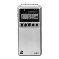
The measuring instruments ALMEMO
®
2290-4 can be configured and
programmed in many different ways. They allow for a connection of many
different sensors, additional measuring instruments, alarm signalisers and
peripheral devices. Due to the large variety of options it is possible that, under
certain conditions, they do not perform as the user would expect. In most cases
this will not be related to a defective device but to operating errors such as
wrong settings or an inadmissible wiring. The following tests should be
performed to correct or to correctly identify the error.
Error: No display data or all display segments are permanently illuminated.
Remedy:Check power supply, recharge battery, switch off and on again,
reinitialise (see 3.3)
Error: False measured values.
Remedy:Thoroughly check the programming of the channel (especially base
and zero point), query the entire programming by means of the
software AMR-Control or the terminal and command P15 (see manual
6.2.3) and f1 P15 (see manual 6.10.1)
Error: Varying meas. values, segment test or blockage during operation.
Remedy: Check cabling for inadmissible electrical connection,
Disconnect external power supply and output modules,
disconnect suspicious sensors and replace them by hand-held
sensors in air or connect dummies and check (short circuit AB at
thermocouples, 100Ω at Pt100 sensors).
If the error is corrected by this, check the wiring,
isolate the sensor if necessary, use electrically isolated power supply,
prevent influences from disturbances by shielding or twisting.
Error: Data transmission via interface does not function.
Remedy:Check interface module, connections and settings:
Are both devices set to the same baud rate and transmission mode
(see 9.1)?
Is the correct COM interface addressed at the computer?
Is the printer set to ONLINE mode?
Are the handshake lines DTR and DSR active?
A small interface tester with LEDs is very useful for checking the data flow
and the handshake lines (during standby mode the data lines TXD and
RXD are on a negative potential of approximately -9V and the diodes are
illuminated green. The handshake lines DSR, DTR, RTS and CTS have a
positive voltage of approximately +9V and the LEDs are illuminated red.
During the data transmission the data lines must flash red).
ALMEMO
2290-4 45
Troubleshooting
 Loading...