Do you have a question about the Ai-Thinker nRF24L01 and is the answer not in the manual?
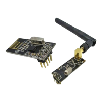
Details the nRF24L01+ transceiver IC, its features, and power efficiency.
Lists key specifications like frequency band, channels, data rate, and pin hardware.
Visual representation of the nRF24L01+ module's pin assignments.
Guidance on radio sensitivity to noise and ensuring circuit stability.
Outlines initial setup, including library installation and MCU preparation.
Step-by-step guide to install the RF24 library in the Arduino IDE.
Wiring and configuration for the NodeMCU as the first wireless node.
Wiring and configuration for the Arduino Nano as the second wireless node.
Demonstrates basic wireless data transmission and reception between nodes.
Arduino sketch for the NodeMCU to transmit data wirelessly.
Shows serial output from NodeMCU during transmit operation.
Arduino sketch for the Arduino Nano to receive data wirelessly.
Displays serial output from Nano during receive operation.
Introduces the availability of sample codes for RF24 module usage.
Details the RF24 'GettingStarted' example code and its usage.
Wiring diagram for the NodeMCU acting as the remote controller.
Wiring diagram for the Nano acting as the local controller.
Visual demonstration of the simple remote control system setup.
Arduino code for the NodeMCU to transmit button states wirelessly.
Arduino code for the Nano to receive states and control an LED.
Connecting external devices like relays or fans to the Nano controller.
Discusses integrating local sensors and actuators with cloud services.
Arduino code for the NodeMCU to connect to the Blynk cloud platform.
Guide on configuring a virtual button in Blynk to trigger actions.
Demonstrates serial output from NodeMCU during Blynk interaction.
Lists important references including Nordic Semiconductor, example sketches, and library forks.
Detailed pin definition and layout for the NodeMCU V1.0.
Detailed pin definition and layout for the Arduino Nano V3.0.
| Frequency | 2.4 GHz |
|---|---|
| Modulation | GFSK |
| Power Supply | 1.9V to 3.6V |
| Interface | SPI |
| Number of Channels | 125 |
| Power Consumption (Power Down) | 900 nA |
| Power Consumption (Standby-I) | 26 μA |
| Data Rate | 2Mbps, 1Mbps, 250kbps |
| Current Consumption (TX) | 11.3mA at 0dBm |
| Transmitting Power | 0 dBm / -6 dBm / -12 dBm / -18 dBm |
| Receiver Sensitivity | -85 dBm |
| Antenna | PCB Antenna or External Antenna |
| Range | Up to 1000m (open space) |
| Current Consumption (RX) | 12.3 mA (2 Mbps) |