INSTALLATION GUIDELINES
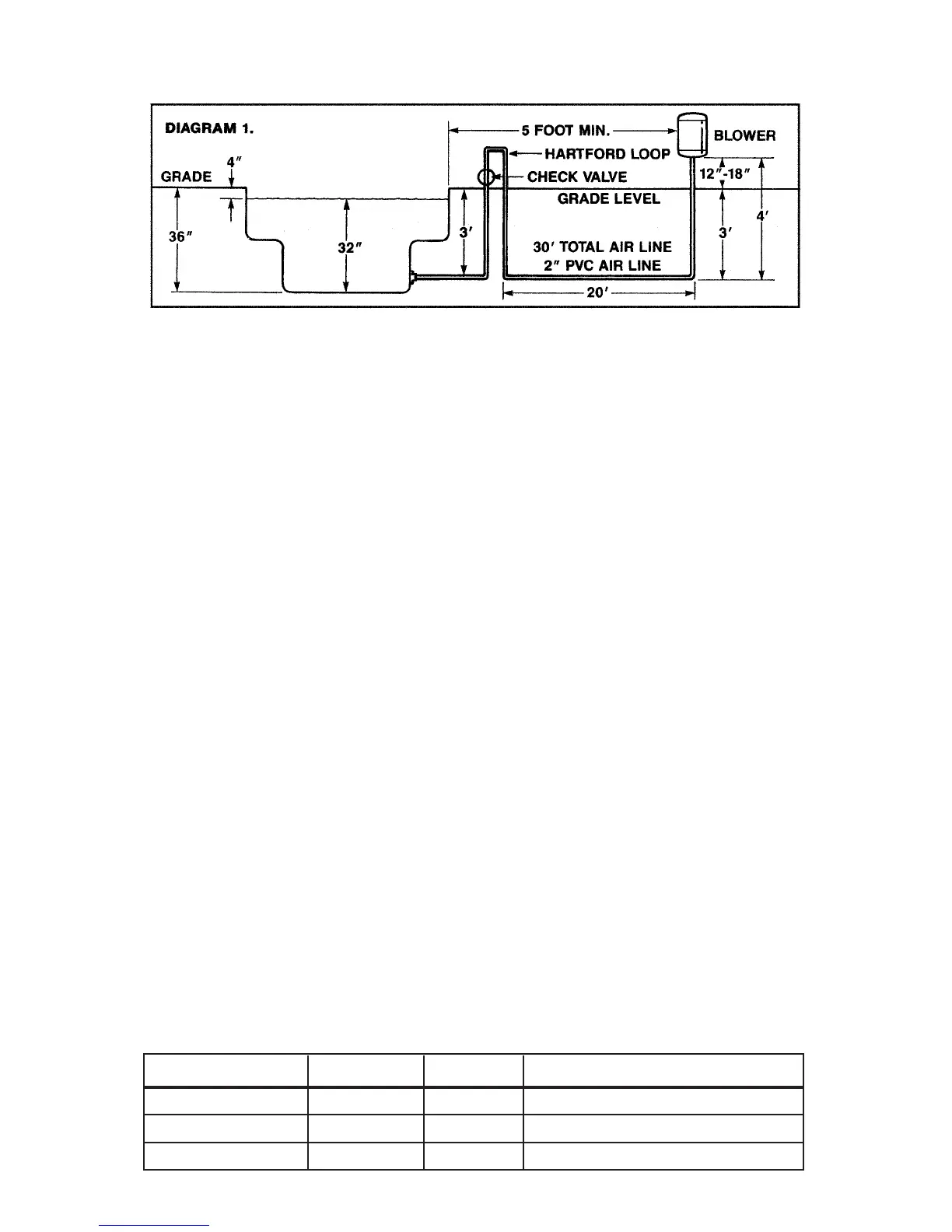
1. Install blower vertically at least one foot (305 mm) above the water line in a well ventilated location free
of debris, chemicals and sprinklers.
2. If the blower is to be installed more than 25 feet from the spa, it is necessary to install a Hartford loop that
is 1 foot above the water line and as close as possible to the spa.
3. Install check valve in a vertical orientation in an easily accessible location above water level so that it can
be serviced.
4. Use 2" supply line from the blower to the spa. At the spa you can reduce down to 1.5" pipe to feed the jets,
air caps, or air channel.
5. Do not glue blower to the supply line. Glue fumes may cause an explosion when the blower is started. You
can secure the blower to the supply line by pre-drilling a small hole through the neck of the blower and
securing with a screw.
6. A loop and check valve must be installed at least 1 foot above water level if the blower is installed below
grade level.
7. A loop and check valve must be installed a minimum of 1 foot above water level when supercharging
water jets.
BLOWER SIZING FOR AIR CHANNEL
There are many variables to consider when choosing the proper size air blower for your spa or hot tub.
These include: water depth, the number and size of air holes, distance of blower from spa, number of 90 and 45
degree turns, and the size of the supply line. Together these variables create back pressure on the blower as
measured in inches of water column (inches H
2
O). Compare your calculations with the chart below to determine
the best size blower for your spa.
1. Measure maximum height of water above lowest section of air channel.
2. For each 10 feet of 2" supply pipe, add 1" (inch) of water pressure.
3. For each 90 degree turn, add 1/2" (inch) of water pressure.
For example:
An 8 ft. in-ground spa with a water depth of 38 inches is located 45 feet away from the equipment.
There are 6 - 90 degree turns and 2 - 45 degree turns. Calculation of total water pressure is as follows:
1. Water height in spa = 38"
2. 45 feet of supply line = 4.5 inches
3. 6 - 90 degree turns and 2 - 45 degree turns = 3.5 inches
Total water height is 46" of water pressure (inches H
2
O).
This spa would require a 1.5 hp blower – see chart below.
BLOWER SIZE VOLTS AMPS INCHES OF WATER ("H2O)
1 HP 120/240 6.7/3.5 UP TO 40" OF PRESSURE
1.5 HP 120/240 8.0/4.0 UP TO 50" OF PRESSURE
2.0 HP 120/240 10.0/6.0 UP TO 65" OF PRESSURE
 Loading...