Do you have a question about the Airbus TMR880i and is the answer not in the manual?
Contact details for TETRA Terminal Customer Support via the Airbus SLC Customer Portal.
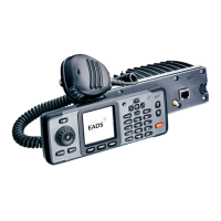
Describes the typical customer radio sales package contents, including transceiver and system cable.
Details the CUR-3 Control Unit sales package, optional accessories, and keymat variants.
References installation guidelines for two configurations utilizing system cables.
Illustrates the enhanced configuration setup using the CA-105 system cable.
Illustrates the basic configuration setup using the CA-156 system cable.
Explains how to operate the TMR880i RC-9 without the CUR-3 control unit, e.g., as a modem.
Details the HSU-6 handset accessory, including its connection and usage.
Describes the HFR-1 handsfree microphone and its connection via CA-105.
Details the PTT-1 handsfree push-to-talk button and its connection to CA-105.
Describes the DLR-3T data cable accessory for data transmission.
Lists vehicle combination antennas for TETRA and GNSS compatibility.
Details the different installation cable options available for the CUR-3 unit.
Describes the AC power supply units suitable for office use with the TMR880i.
Details the MPR-4 speaker microphone, optionally included in CUR-3 packages.
Describes the HFS-10 loudspeaker, part of some CUR-3 sales packages.
Details the HFS-11 15W loudspeaker, an optional accessory.
Describes the HHR-1 swivel mount for securing the CUR-3 control unit.
Lists miscellaneous other parts available for vehicle installation.
Details the installation plate accessory for mounting the radio unit.
Specifies the 5A 125°C rated fuse accessory required for power connections.
Describes the SS-4 start-stop plug, used for E2EE smart cards in older radios.
Describes the connectors located on the back-front panel of the TMR880i radio unit.
Describes the connectors located on the front panel of the TMR880i radio unit.
Details the connectors available on the CUR-3 control unit.
Explains how to connect and use various audio accessories with the TMR880i.
Details the cables and connector options for connecting speaker microphones.
Describes the MPR-4 speaker microphone connector and its cable connection.
Details the MPR-1 speaker microphone connector and its cable connection.
Describes the 26-pin system cable connector and its data interface functions.
Details the 26-pin D connector for the CUR-3 external control unit interface.
Describes the 26-pin D connector for various I/O auxiliary accessories.
Details the RJ45 connector interface for external smart card readers.
Describes the SMA connector interface for active GPS antennas.
Details the TNC connector interface for TETRA RF antennas.
Describes the connector interface for smart cards or SIM cards.
Guides on selecting the optimal site and installing the vehicle antenna.
Details criteria for choosing a safe and effective antenna mounting location on the vehicle.
Provides steps for mounting the antenna and connecting its coaxial cable.
Covers the assembly procedure for the CUR-3 control unit and its components.
Instructs on correctly assembling the installation cable for the CUR-3 unit.
Details connecting speaker microphone cables for MPR-1 and MPR-4 models.
Guides on attaching the HHR-1 swivel mount to the CUR-3 control unit.
Explains installing CUR-3 into a DIN slot using the dedicated installation set.
Details preparing the DIN slot installation bracket, including electrical and manual unlocking.
Guides on preparing the DIN slot installation adapter with screws for mounting.
Details attaching the CUR-3 unit into the assembled DIN slot installation set.
Provides instructions for mounting the TMR880i unit using an installation plate.
Covers critical aspects of vehicle power distribution and supply voltage requirements for the TMR880i.
Details proper grounding procedures, emphasizing firm connections and cleaning.
Explains IGN power control using the vehicle's ignition key and its interaction with I/O lines.
Details the various interfaces and connectors of the CA-105 system cable.
Provides guidance for professional modification of installation cables for space-limited scenarios.
Presents the circuit diagram for the helmet cable's connections and interface.
Provides a detailed description of the helmet cable's interface, including microphone and speaker.
Explains the helmet cable's microphone input interface, its balanced type, and filtering.
Lists the electrical specifications for the microphone input, including impedance and biasing voltage.
Describes necessary modifications and external amplifiers for using a dynamic microphone.
Provides guidance on selecting RF noise-resistant electret microphone capsules.
Details the helmet cable's speaker output interface, noting its balanced type and protection.
Lists the electrical specifications for the speaker output, including load impedance and output power.
Describes the three control signals (MC_PTT, HELMET_SWITCH, SPM_MUTE) for the helmet cable.
| AM/FM Tuner | No |
|---|---|
| Apple CarPlay | No |
| Android Auto | No |
| Channel Spacing | 25 kHz |
| TETRA Standard | ETS 300 392-2 |