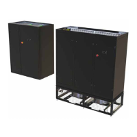
SmartCool
TM
- D
Precision Air Conditioning
160
Precision Air Conditioning
Installation, Maintenance and Commissioning Manual :6877419 02/2013
¡ ç
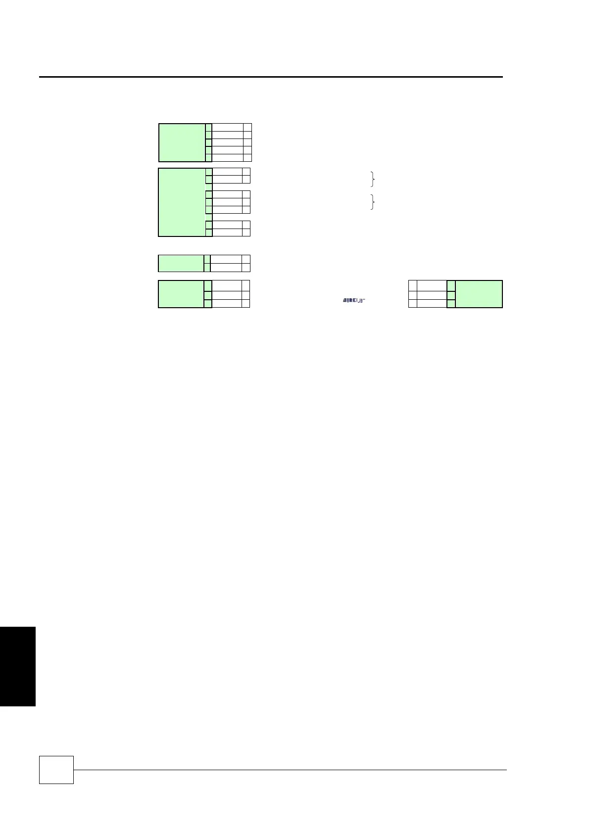
Mains Incoming Supply 400V / 3PH + N / 50Hz
¡ è
Volt Free Alarm N/O
Non-Critical Alarm
¡
è
Volt Free Alarm N/O
Critical Alarm
¡ ç
Healthy in N/C Condition
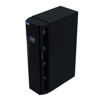
INDOOR
UNIT
502
¡ è
Remote On/OFF
522
¡ ç
INDOOR
UNIT
Rx-/Tx-
¡ çè
Use Awg20/22 twisted pair (with overall shield)
cable, Belden ref. 8762 (Airedale ref:
6110316), or equivalent, for
network
çè ¡
Rx-/Tx-
INDOOR
UNIT
N + 1
Rx+/Tx+
¡ çè çè ¡
Rx+/Tx+
GND
¡ çè çè ¡
GND
In line with IEE Wiring Regulations, the following should be observed:
Extra low voltage control cables (ELV) and mains power cable should be segregated by a
minimum distance of 50mm
If cables must cross, it is recommended that they cross at right angles
Airedale recommends that ELV cables are screened at one end to earthed enclosures
C0C0