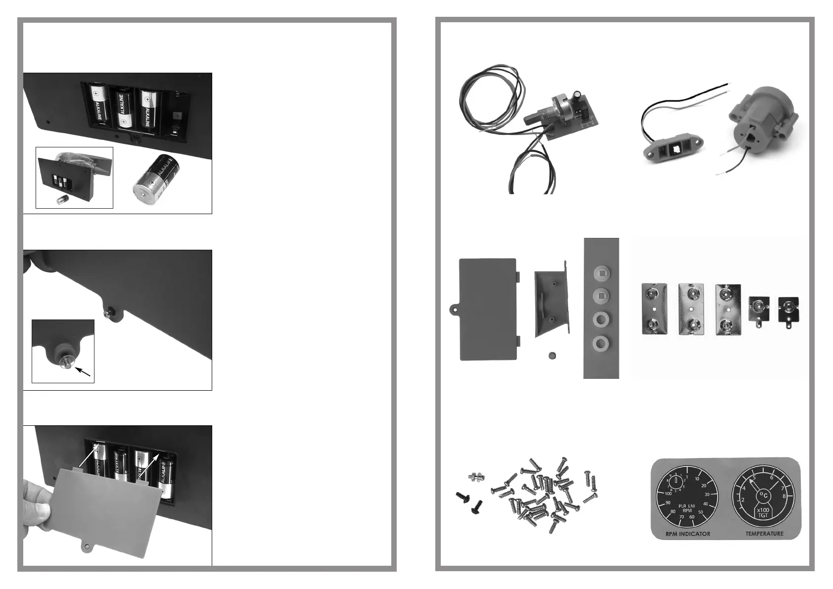
Kit Parts - Securing screws and Instrument Panel Sticker
Kit Parts - Circuit board and voltage regulator,
power switch and fan motor
Kit Parts - Battery cover, pylon half, plug, engine spindle
spacers and washers and battery terminals
5
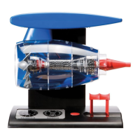
Assembly sequence 64
Assembly sequence 65
Assembly sequence 66
Note: Batteries are not supplied
Four batteries,1.5 volt - size C, are
required to operate the completed
Jet Engine model
To ensure a power suppy to the
motor, the batteries must be
correctly installed into the battery
compartment as indicated
Push the securing bolt, for the
battery box cover plate, through the
hole in its lower lug.
Turn the cover plate over and place
the clear retaining washer onto the
bolt to secure the bolt to the cover
plate
Push the locating lugs of the
battery box cover into the locating
holes of the battery box/base plate
jet engine
28
 Loading...