Assembly sequence 19
Assembly sequence 20
Assembly sequence 21
The battery cover securing nut and
blanking plug are positioned into
the aperture as indicated in
assembly sequences 20 and 21
Place the nut into the aperture and
allow it to drop inside
Push the plug fully into the top of
the aperture to lock the securing
nut permanently inside aperture
13
Assembly sequence 40
Assembly sequence 41
Assembly sequence 42
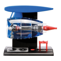
Push the collar of the air directional
tubing onto the fan motor housing
unit.
Note: The collar is recessed to fit
onto the motor housing. Ensure the
collar is pushed securely in position
over the two halves of the fan outer
casing to hold them together
Connect the motor electric cables
to the engine light unit supply
cables by twisting them together as
indicated, red to red and black to
black
Cut two pieces of shrink sleeve to
length and thread over the joined
cables as indicated
jet engine
RED
BLACK
BLACK
RED
20
 Loading...