EasyManua.ls Logo

Airstream TC5-2V4SA User Manual

Airstream TC5-2V4SA
60 pages
To Next Page IconTo Next Page
Page #1 background imageLoading...
Page #1 background image
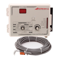
TC5-2V4SA
Temperature Controller
USER'S MANUAL
HEATER 1
OFF. / DIFF. (T )
(T )
M 890-00103 rev. 06
REV. 00

Questions and Answers:

Airstream TC5-2V4SA Specifications

General IconGeneral
Enclosure RatingIP65
InputThermocouple
OutputRelay
Supply Voltage100-240 VAC
Control TypeOn/Off
DifferentialAdjustable
Sensor TypeThermocouple, RTD

Summary

PRECAUTIONS

FEATURES

Display and Indicators

Features a three-digit display and pilot lights for status monitoring.

Control Functions

Includes temperature/ventilation curves, minimum ventilation, and humidity compensation.

System Configuration

Supports various motor types, probe inputs, and heater configurations.

Operational Modes

Offers test mode, overload protection, and computer control capabilities.

LOCATION OF THE CONTROLS

CONTROLLER STATUS LEDS

INTERNAL SWITCHES

INSTALLATION

Mounting Instructions

Details on how to mount the enclosure securely on a wall.

Connections

Guidance on wiring and connecting the controller and its components.

Alarm Connection

Information on connecting alarm types to NO or NC terminals.

MOTOR TYPES

Selecting Stage 1 Motor Type

Procedure to select the correct motor type for Stage 1.

Selecting Stage 2 Motor Type

Procedure to select the correct motor type for Stage 2.

HEATING / COOLING OPTION

TEMPERATURE PROBES

Connecting Temperature Probes

Instructions for connecting temperature probes to the controller inputs.

Extending Probe Cables

Guidelines for extending probe cables up to 500 feet.

Identifying Defective Probes

How to identify and troubleshoot defective temperature probes.

CHANGING PARAMETER SETTINGS

Using the Controller Display

Explains flashing vs. non-flashing values and relative/absolute temperature display.

Relative and Absolute Value Display

Details how parameters are displayed as relative and absolute temperatures.

Locking Parameter Settings

How to lock settings to prevent accidental modification.

TEMPERATURE SETTINGS

Temperature Unit Selection

Setting the display to Celsius or Fahrenheit units via internal switch.

Viewing Room Temperatures

How to view room and individual probe temperatures.

Viewing Individual Probe Temperatures

Detailed steps for viewing individual probe readings and states.

Viewing Min/Max Temperatures

How to view recorded minimum and maximum temperature values.

TEMPERATURE SET POINT

Adjusting the Temperature Set Point

Procedure to adjust the target room temperature.

TEMPERATURE CURVE

Specifying the Temperature Curve

Steps to define the six points for the temperature curve.

Activating the Temperature Curve

How to activate the defined temperature curve.

Viewing and Adjusting Curve Day Number

How to view and adjust the current set point and day number on the curve.

Deactivating the Temperature Curve

Steps to deactivate the active temperature curve.

VENTILATION SETTINGS

Cooling Operation Overview

Diagram and explanation of cooling stages operation.

MINIMUM VENTILATION CYCLE

Minimum Ventilation Cycle Settings

How to configure continuous, stopped, or intermittent operation.

Adjusting Stage 1 Minimum Speed

Setting the minimum speed percentage for Stage 1 fans.

Stage 1 Time On and Time Off Adjustment

Configuring the on/off times for the minimum ventilation cycle.

HUMIDITY COMPENSATION

Viewing Relative Humidity Readings

How to view current, minimum, and maximum relative humidity readings.

Adjusting Relative Humidity Set Point

Setting the humidity level that triggers compensation.

Adjusting Minimum Speed Compensation

Setting the percentage increase in minimum speed based on humidity.

Activating/Deactivating Humidity Compensation

Turning the humidity compensation feature on or off.

MINIMUM VENTILATION SPEED CURVE

Interaction Between Temperature and Speed Curves

Rules for activating minimum speed curves with temperature curves.

Specifying the Minimum Speed Curve

Steps to define the six points for the minimum speed curve.

Activating the Minimum Speed Curve

How to activate the defined minimum speed curve.

Viewing Current Minimum Speed and Day

How to view current minimum speed and day number.

Deactivating the Minimum Speed Curve

Steps to deactivate the active minimum speed curve.

DIFFERENTIAL SETTINGS

Adjusting Stage 1 Bandwidth

Setting the temperature interval for Stage 1 speed adjustment.

Adjusting Stage 2 Offset

Setting the temperature difference for Stage 2 fan start.

Adjusting Stage 2 Bandwidth

Setting the temperature interval for Stage 2 speed adjustment.

Adjusting Stage 2 Minimum Speed

Setting the minimum speed percentage for Stage 2 fans.

Adjusting Stage 3-6 Cooling Differentials

Setting cooling differentials for constant-speed fans Stages 3-6.

DE-ICING OF STAGE 2 FANS

Adjusting De-icing Cycle Time

Setting the time lapse between de-icing operations.

Adjusting De-icing Time

Setting the duration of de-icing operations in seconds.

MIST COOLING

Adjusting Mist Differential

Setting the temperature variation for mist unit on/off points.

Adjusting Mist Offset

Setting the temperature difference from set point for mist unit turn off.

Adjusting Mist Timer Settings

Configuring time on and time off for mist unit operation.

Adjusting Humidity Turn Off Level

Setting the humidity level to turn off mist units when compensation is active.

HEATER SETTINGS

Cascading Heaters Operation

Explanation of how heaters operate in sequence.

Zoned Heaters Configuration

Configuration for zoned heaters and probe assignments.

Adjusting Heater Offsets

Setting the temperature difference for heating units to turn off.

Adjusting Heater Differentials

Setting temperature difference for heater units turn on/off.

Adjusting Max Zone Temperature Difference

Setting max temp difference for zoned heating protection.

ALARM SETTINGS

Adjusting High and Low Alarm Settings

Setting low and high alarm offsets relative to the set point.

TEST MODE

Entering Test Mode

Steps to activate the controller's test mode.

Exiting Test Mode

Steps to safely exit the controller's test mode.

TROUBLESHOOTING GUIDE

Display Not Working

Troubleshooting steps for a non-functional display.

Display Shows Letter "P"

Diagnosing and resolving the display showing the letter 'P'.

Defective Probe Pilot Light On

Steps for identifying and replacing defective probes.

Sudden Temperature Variations

Causes and solutions for temperature reading fluctuations.

Stage 1 or 2 Fans Not Running

Troubleshooting steps when Stage 1 or 2 fans fail to operate.

Stage 1 or 2 Fans Run Continuously

Diagnosing and fixing fans running continuously at full speed.

Stage 1 or 2 Fans Run Erratically

Troubleshooting erratic fan operation for Stage 1 or 2.

Stage 1 Fans Not Stopping in Min. Ventilation Cycle

Resolving issues with Stage 1 fans not stopping in the minimum ventilation cycle.

Stages 3, 4, 5, or 6 Not Operating

Troubleshooting steps when Stages 3, 4, 5, or 6 are not operating.

TECHNICAL SPECIFICATIONS

FACTORY SETTINGS

GLOSSARY

NOTES