4
1
2
3
a
b
c
5
SERVICE INFORMATION
25
REMOVING THE COMBUSTION CHAMBER
• Remove the AIRTRONIC cover.
Remove the ange seal.
Take the AIRTRONIC out of the outer case (lower part).
• Remove ECU (see previous pages).
• Remove glow pin (see previous pages).
• Remove combustion air blower (see previous pages).
Unscrew the fastening screws.
For AIRTRONIC D2 = 3 fastening screws
For AIRTRONIC D4 = 4 fastening screws
Pull the combustion burner out to the front and remove the
burner’s thermal insulator from the heat exchanger.
When reassembling the combustion burner, the thermal
insulator, must always be replaced.
Tighten the self tapping fastening screws of the combustion chamber with a
torque of 5
+0.5
Nm. (44 in•lb)
If the heat exchanger is being replaced, the overheat/ame
sensor must be dismantled and mounted to the new heat
exchanger (see previous pages).
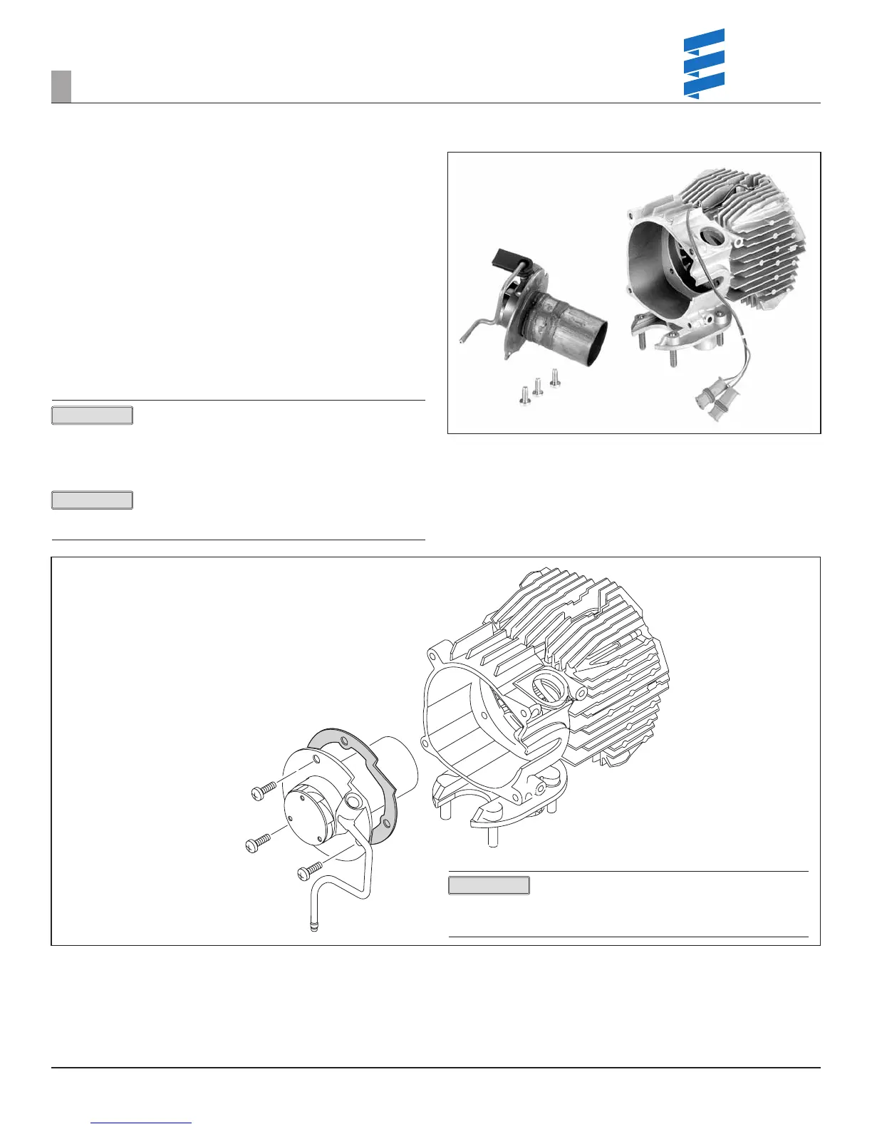
Figure 38
1 Combustion burner
2 Thermal insulator between combustion burner and heat exchanger, must
always be replaced if burner is removed from the heat exchanger.
(Holes not threaded)
3 Heat exchanger
4 Self tapping fastening screws.
AIRTRONIC D2 = 3 fastening screws
AIRTRONIC D4 = 4 fastening screws
Figure 37
a Combustion burner
b Heat Exchanger
c Fastening screws
AIRTRONIC D2 = 3 fastening screws
AIRTRONIC D4 = 4 fastening screws
Holes in heat exchanger that fasten the burner tube are
not tapped.
When fastening a burner to a new heat exchanger it is
recommended to use new screws.
PLEASE NOTE!
PLEASE NOTE!
REVISION LEVEL A - 09/09/15
PLEASE NOTE!
 Loading...