18
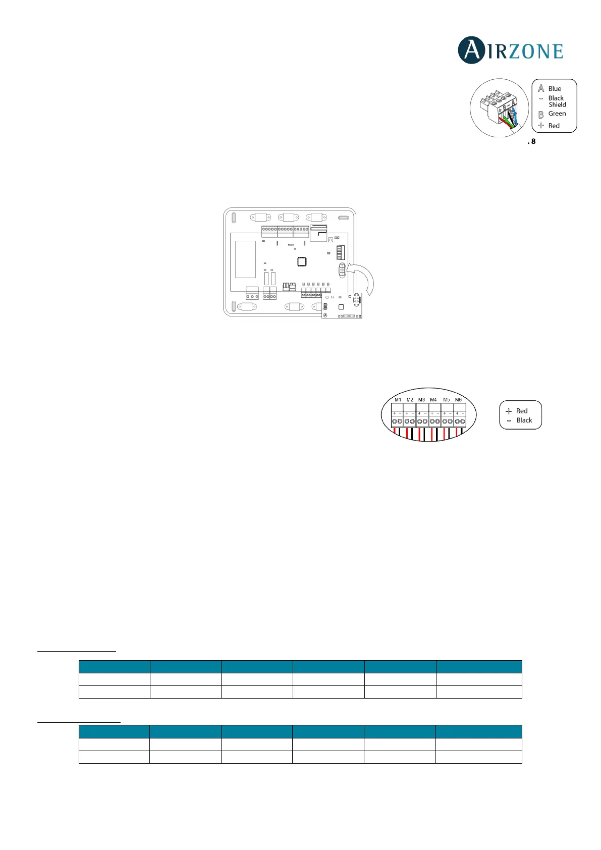
It has a 4-pin terminal to connect the AC unit bus. The connection for these elements is point-to-
point. Attach the wires with the terminal screws following the color code (Fig. 8).
Note: For elements externally powered at 110/230 Vac, for the communications, it is only necessary to
connect the poles "A", "B" and “Shield” of the communication bus. Use the shield only on the connector of
the main control board.
To connect integrated gateways, disconnect the AC unit bus terminal and insert the connector and the fixing post of the
gateway (Fig. 9).
Fig. 9
Actuator outputs
12-V actuator outputs allow you to connect Airzone motorized elements and manage them from the main control board (up
to 8 actuators per board, up to 2 engines per output).
There are 6 two-pin terminals available to connect the motorized dampers.
Attach the wires with the terminal screws following the color code (Fig. 10).
Alarm input
This input closes all the dampers and imposes Stop mode when there is an alert. This input is configured as normally closed.
For proper operation of the system, this contact is supplied with a bonding jumper.
Temperature probe connector
It measures the outdoor temperature through an external probe. We recommend the use of this probe when using
electromechanical units or NON-Inverter units (when it is necessary to control the return temperature of the units).
CMV/Boiler connector
This output can be configured as controlled mechanical ventilation control or boiler control. (See Blueface Advanced
Configuration Menu, system parameters)
CMV configuration
Boiler configuration
Relay specs: I
max
= 1 A at 24/48 Vac, voltage-free. Note that to control elements with a greater power, it is recommended to use
contactors in accordance with the power required.
 Loading...