25
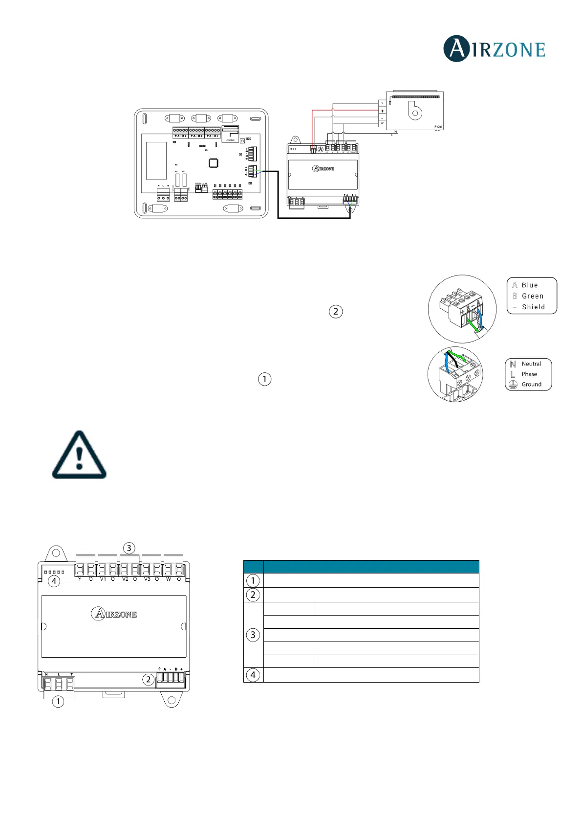
Connection diagram, 4-pipe installation
Fig. 32
Control relay specs: I
max
= 10 A at 110/230 Vac, voltage-free. Note that to control elements with a greater power, it is
recommended to use contactors in accordance with the power required.
It has a 5-pin terminal to connect it to the AC unit bus of the main board . Attach the wires
with the terminal screws following the color code (Fig. 33). Use the shield only on the
connector of the main control board.
It is connected to the module through a 3-pin terminal . Attach the wires with the terminal
screws following the color code (Fig. 34).
According to the current local and national regulations, it is mandatory to add a switch (or other element
to disconnect the system) to the external supply wiring so that a constant separation between poles is
guaranteed. The system will restart automatically if the supply is eventually turned off.
independent circuit from the controlled system for the power supply.
AIRZONE CONTROL GATEWAY-3 SPEEDS FANCOIL (AZX6FANCOILZ)
Fig. 35
Power supply
AC unit bus
Status LEDs
 Loading...