27
Control relay specs: I
max
= 10 A at 110/230 Vac, voltage-free. Note that to control
elements with a greater power, it is recommended to use contactors in accordance
with the power required.
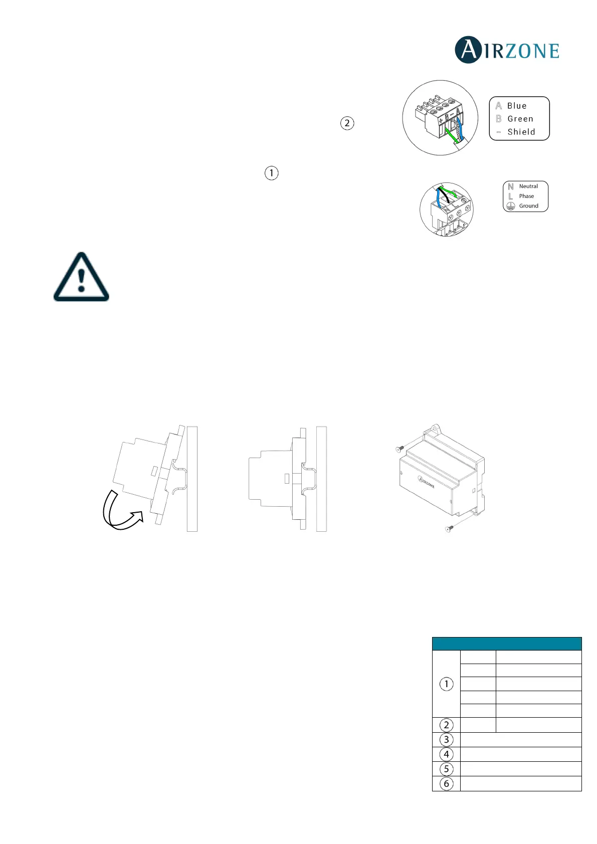
It has a 5-pin terminal to connect it to the AC unit bus of the main board . Attach
the wires with the terminal screws following the color code (Fig. 40). Use the shield
only on the connector of the main control board.
It is connected to the module through a 3-pin terminal . Attach the wires with the
terminal screws following the color code (Fig. 41).
According to the current local and national regulations, it is mandatory to add a switch (or other element
to disconnect the system) to the external supply wiring so that a constant separation between poles is
guaranteed. The system will restart automatically if the supply is eventually turned off.
independent circuit from the controlled system for the power supply.
CONTROL GATEWAY FOR ELECTROMECHANICAL UNITS (AZX6ELECTROMEC)
Assembly
The electromechanical control gateway is mounted on DIN rail (Fig. 42) or on wall (Fig. 43). This module is integrated into the
AC unit bus of the main board. It has a 4-pin terminal. Disconnect the terminal to which you want to connect to the module
and fit the connector. It should be placed and mounted in accordance with the current electrotechnical regulations.
Fig. 42 Fig. 43
Note: To remove the module on DIN rail, pull the tab down to release it.
Connection
The electromechanical control gateway connects to the AC unit bus of the main board (Fig. 44).
Microswitch
AC unit bus
AC unit probe
 Loading...