Do you have a question about the Aiwa NSX-AV80 and is the answer not in the manual?
Details FM, AM, and SW tuning ranges and sensitivities.
Covers amplifier power output, distortion, and speaker system details.
Specifies CD player performance and general unit parameters.
Guidelines for handling the optical block safely during servicing.
Lists primary electronic components like ICs, transistors, and diodes.
Details components for KEY, AMP, PT, and DECK circuit boards.
Explains the coding system for chip resistors.
High-level functional diagrams of the system's main sections.
Functional block diagrams for integrated circuits.
Illustrates the internal wiring of the main circuit board (U).
Shows the wiring connections for the front circuit board.
Details the wiring for the MVR and Amplifier boards.
Covers wiring for the tape deck and PT circuit boards.
Detailed electronic schematics for the main circuit board (U).
Schematics related to the FM/AM/SW tuner sections.
Electronic schematics for the front circuit board.
Schematics for the MVR and Amplifier circuit boards.
Details the pin functions and descriptions for IC LC866440W-5A91.
Details the pin functions and descriptions for IC LC72131D.
Details the pin functions and descriptions for IC NJW1102AFG1.
Procedures for adjusting tuner frequency and tracking.
Procedures for adjusting tape speed, azimuth, and playback levels.
Practical service figures for tuner adjustments and specifications.
Practical service figures for deck adjustments and specifications.
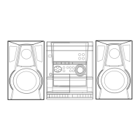
Diagrams showing the physical assembly of the unit.
List of all mechanical parts used in the unit.
Illustrates the correct placement of springs in the mechanism.
Diagram showing the assembly of the tape transport mechanism.
List of parts specific to the tape transport mechanism.
Lists included accessories and package contents.
Provides definitions for technical terms used in the manual.
| Brand | Aiwa |
|---|---|
| Model | NSX-AV80 |
| Category | Stereo System |
| Language | English |