9-79-0752-G-0
9-40-0752-G
inMusic Brands
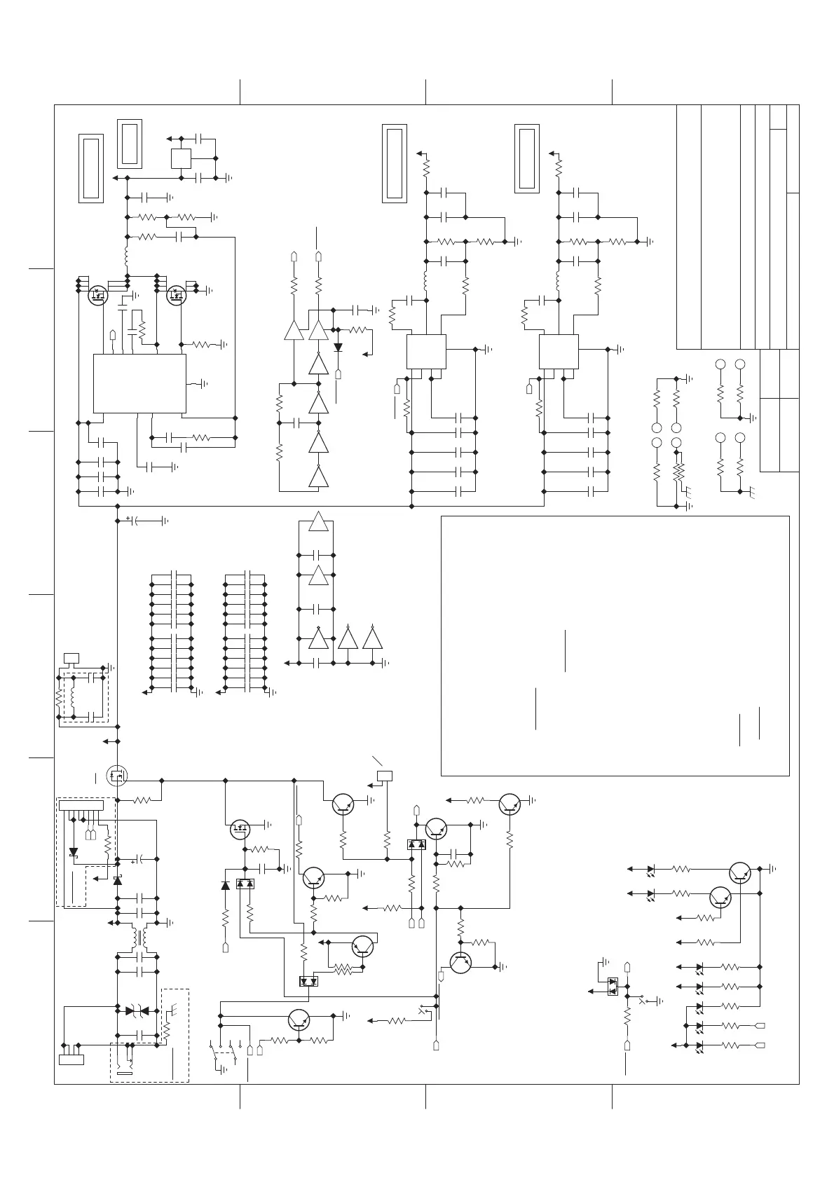
AZ01 CARRIER BOARD
AZ01CRG02A.sch
4/18/2018
MJS
C
15
OFSHEET:
SIZE:
DATED:
DATED:DRAWN:
RELEASED:
SCALE:
FILENAME:
PART NUMBER:
TITLE:
COMPANY:
A
B
D
C
A
B
C
D
654321
ASSY NUMBER:
Copyright 2018 inMusic Brands
+5V/7A
SoM
USB 3.0 Jacks
VBAT_WL (WIFI/BT)
HUB_AVDD (USB HUB)
VCC_3V
VCC_TP (Touch Panel)
VJM_3V3 (USB-SATA IC)
VCC_SD (SD Card socket)
LCD backlight
+1.8V
+3.3V/1A
pull-up to 1.8V located on SOM
Recovery
from external PCB
to PMIC
From SoC
Power
Power up:
*Power switch pressed
*System Pass-FET turns on
System
Pass-FET
*5V supply rises within 3ms and asserts POWER_GOOD
*3.3V regulator output rises
*If the power button continues to be held down,
*Signal "PWR_EN" rises to >=1.4V
(it has 900k
(Vih_min of PMIC input pin)
*System-on-module powers on when:
(the open drain output goes hi-z))
*System-on-Chip asserts PWR_HOLD a few seconds later, latching module power
Power down:
*System-on-Chip writes shutdown command to PMIC
(see PMIC datasheet p29) on, as well as the System Pass-FET
to PMIC
*POWER_GOOD is pulled up to 3.3V
*Once power switch is released, PMIC_PWRON and POWER_GOOD return to hi-z
*Signal "PMIC_PWRON" pulled to ground through 50k
*Further button presses/releases have no impact on PMIC, but they are still
also passed to SoC via
the PMIC on net PWR_KEY
*Master Pass-FET turns off
Reset:
USB 2.0 headers
*active RESET signal pulls PWR_EN low, turning off most supplies generated by PMIC
7.2x7.5mm
3x3mm
5x6mm
3x3mm
Recovery (boot-loader access:)
*http://radxa.com/Rock2/square_bb/loader_mode
*With board powered on, connect USB OTG port to host PC
*Assert RECOVERY for 5 seconds
*Assert and then unassert Reset (mininum assertion time should be short, but it is TBD)
1.8V LDO
Delay
Reset
from external PCB
keep System Pass-FET on for at least 1s after
every power button or reset button
press/release event
asserted a few secs
*Delay circuit is charged, keeping System Pass-FET
powered for ~5s after button release
from external PCB
Active: drive to 3.3V
Inactive: pull low or go hi-z
*Delay circuit is charged, keeping System Pass-FET
powered for ~5s after button release
~5s
Active: pull low
Inactive: hi-z
Active: pull low
Inactive: hi-z
passed to SoC and can have a software-defined function
*PWR_HOLD goes unasserted as System-on-Chip becomes (mostly) unpowered
*RESET button is released, so PWR_EN is no longer actively pulled low
*System-on-Chip asserts PWR_HOLD ~1s later, latching module power +
*unassert RECOVERY
8A
load to GND)
System Pass-FET on
VCC_WL (WIFI/BT)
*system should boot into Flash loader mode
+1.25V/1.5A
USB Hub
USB-SATA bridge
~725kHz
Mounting Holes
Jack side
Interior mounting Holes
Plane decoupling
to SoC
after PMIC enable
To Control surface
Battery
CHARGE
DISCHARGE
GND
Internal
AC/DC
DISCHARGE
GND
GND
GND
VCC
VCC VCC
GND
DC barrel
SDA
SCL
To/From
From
(Charge path
need series diode
Drain +3.3V_SOM that may still
be driven by USB-to-UART debugger
protection built in to pack)
Keep board powered while programming
if SoM fails to assert pwr_en during loader mode,
or while SoM is absent from slot
Heatsink Mounting holes
SLOW/FAST
Leoco 2011P08V000
Exclude
MG01
JP07
JC11
Exclude
MG01
*PWR_HOLD goes unasserted as System-on-Chip becomes (mostly) unpowered
HG03
isolated
non-isolated
JP08
EMI Countermeasure starting
HG02
1
2
3
J5
JKKD-01H2T-20
D1
26V
1
4
3
2
L3
S
G
D
Q2
1
GND
2
OUT
3
IN
U2
PJ1117CW-1.8
C5
0.1uF
16V
C6
0.1uF
16V
Q16
MBT4401
R59 10.0
S2
R28
100K
C63
47uF
10V
1
VDD
2
EN/SS
3
PGOOD
4
COMP
5
FB
6
BOOT
7
HDRV
8
SW
9
LDRV/OC
10
BP
11
GND
U8
TPS40304
1
2
3
4
5
6
S1
R62100K
R61
10.0K
Q14
MBT4401
R63
10.0K
R27 51.1K
Q30
MBT4403
R64 10.0K
R66 10.0K
R65
2.74K
C83
180pF
50V
R67
8.87K
C89
0.033uF
50V
C90
8200pF
50V
C91
4.7uF
25V
C92
4.7uF
25V
C94
4.7uF
25V
C95
1uF
25V
C96 1uF
10V
C97
2200pF
50V
R68
237
R69
10.0K
R70
1.37K
G
S
D
Q6
CSD18537NQ5A
TEXAS INSTRUMENTS
G
S
D
Q7
Infineon
BSZ100N03MS
L4
3.3uH
R71
4.75K
R73
2.00M
S3
Q18
MBT4401
R60
10.0K
C69
4.7uF
10V
R72
499
G
S
D
Q8
2N7002
LED1
RED
LED2
RED
Q17
MBT4401
Q23
MBT4401
R98
1.00K
R99
1.00K
R891.00K
R881.00K
R90-A 1K
R90-B 1K
R90-C 1K
R90-D 1K
R911.00K
LED7
RED
LED3
RED
LED4
RED
LED5
RED
LED6
RED
12
3
D3
BAV99
C24
22pF
50V
R92
22.1K
R93
36.5K
C84
0.1uF
50V
C85
10uF,25V
C86
22uF
6.3V
C87
22uF
6.3V
C93
10uF,25V
1
AAM
2
IN
3
SW
4
GND
5
BST
6
EN/SYNC
7
VCC
8
FB
U6
MP2315
R16 75.0K
C82
0.1uF
50V
R94100K
C4
33pF
50V
R100
40.2K
R101
12.7K
C98
0.1uF
50V
C99
10uF,25V
C108
22uF
6.3V
C109
22uF
6.3V
L5
4.7uH
C110
10uF,25V
1
AAM
2
IN
3
SW
4
GND
5
BST
6
EN/SYNC
7
VCC
8
FB
U1
MP2315
R104 33.2K
C111
0.1uF
50V
R105100K
C112
1000pF
50V
C113
560pF
50V
C114
560pF
50V
1
2
3
D4
BAV70
1
2
3
D14
BAV70
1
2
3
D11
BAV70
R107 0
R108 0
R109 100K
12
U37-A
34
U37-B
56
U37-C
13 12
U37-F
R110 2.21K
98
U37-D
v+
v-
14
7
U37-G
11 10
U37-E
L9
2.2uH
C3
0.1uF
50V
C23
0.1uF
50V
R102 20.0
R119 20.0
C115
100pF
50V
C116
0.1uF
16V
R1 0
Z3
Z4
R127 DNS
R128 DNS
Z5
R129 0
Z6
R130 0
C118 1000pF
50V
C119 1000pF
50V
C120 1000pF
50V
C121 1000pF
50V
C123 1000pF
50V
C124 1000pF
50V
C125 100pF
50V
C132 1000pF
50V
C133 1000pF
50V
C134 1000pF
50V
C135 1000pF
50V
C136 1000pF
50V
C137 1000pF
50V
C127 100pF
50V
C128 100pF
50V
C129 100pF
50V
C130 100pF
50V
C131 100pF
50V
C138 100pF
50V
C139 100pF
50V
C140 100pF
50V
C141 100pF
50V
C142 100pF
50V
C143 100pF
50V
1
24
U40-A
R145
100K
1
24
U39-A
VCC
GND
3
5
U39-B
74AHC1G126
C164
0.1uF
VCC
GND
3
5
U40-B
74AHC1G126
C165
0.1uF
R111 47.5
R112 47.5
C88 0.1uF
16V
R122 10.0
1
2
J19
1
2
3
4
J13
1
2
3
4
5
6
7
8
J29
D2
PMEG3050BEP
C126
150uF,25V
Q26
MBT4401
R52
100K
R124
100K
C77
1uF
10V
Q28
MBT4401
R148 10.0K
R149
200
R150
1.00M
R157 1.00K
1
2
J30
Z8
Z10
Z9
Z7
R164
499
R165 DNS
D8
1N4148W
R168 1.00K
D9
DNS
D13
PMEG3050BEP
R23
10.0K
R1710
R1720
C168
1000pF
50V
C169
1000pF
50V
C170
10uF,25V
C171
10uF,25V
C172
47uF, 50V
R173 DNS
R176 DNS
R177 DNS
R178 DNS
R179 DNS
Q27
MBT4401
R9
1.00K
R202
499
C180
0.1uF
16V
L18
4.7uH
C181
10uF,25V
C182
10uF,25V
CHGND
GND
+1.8V
GND
RECOVERY
+1.8V
PWR_EN
PWR_HOLD
+V_WALL
POWER_GOOD
POWER_GOOD
PMIC_PWRON
GND
+3.3V
GND
GND
GND
RESET
+3.3V
+3.3V_SOM
LED_STATE1
+5V +3.3V +1.8V +1.25V
LED_STATE2
+5V +5V
+1.25V
GND
GND
+3.3V
GND
GND
+5V
GND
REG_SYNC
REG_SYNC
REG_SYNC
REG_SYNC
ADKEY_IN
CHGND
+3.3V
+5V
GND
POWER_IN
+5V+5V
+5V
+V_WALL_SW
I2C3_SDA
I2C3_SCL
USB_HUB_RESET
+3.3V_SOM
+3.3V
+3.3V_SOM
PWR_OFF_DELAY
CHGND
POWER_IN
POWER_IN
GND

 Loading...