Frequenzgong
des verhollten
Signols:
50
bis 8.000
Hz
Störobstond:
unverholltes Signol:
Gertiusch
> 78
dB
Lineor
>
78 dB
verholltes
Signol:
Geröusch
=
71 dB
Lineor >67 dB
Entzerrbereiche:
unobhöngig
ftlr
[eden
Konol
einstellbor
Tiefenbereich:
+/-
10 dB bei 100 Hz
Mittenbereich:
+/-
15
dB
Gütebereich des Filters:
I bis
l0
Mittenfrequenz
des Filters:
500
bis
5.000
Hz
Netzsponnung:
120/220 Volt, 50
-
60
Hz
Abmessungen:
483x134x254mm(BxHxT)
Gewicht:
5,5
kg nefto
8,6 kg
brutto
3.
BETRIEBSHINWEISE
Bevor dos BX 5
on dos
Netz
ongeschlossen wird, kontrollieren Sie
bitte, ob die zur Verfügung
stehende
Netzsponnung
zwischen den
Werten 93 bis 127
Volt oder
187 bis 253
Volt
(Wechselsponnung)
liegf .
Vom Werk ist die Betriebssponnung
des
BX
5E ouf
"220
V"
einge-
stel
lt. Dos BX
5El ist ouf
"
l l 0
V" eingesfel lt.
Sollte
es
notwendig
sein, die Betriebssponnung
des
BX
5 zu ver-
öndern, gehen
Sie wie in Punkt 5.2 beschrieben
vor.
3. I .lnbetriebnohme:
Dos BX.-Eot
-keine
speziellen Arretiervorrichtungen
ftir den Trqns-
port.
Wir empfehlen ollerdings,
die Originolverpockung
fijr
etwoige
löngere Tronsporte
zu verwenden. Sofort noch
dem Auspocken
und
noch Beochtung
von Pkt.
3 konn dos Geröt
eingescholtet werden.
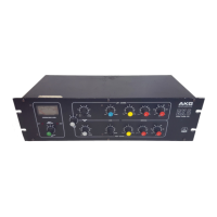
3.2. Anschli.isse:
Der
A-il6ii-U
,/on
Tonquellen
bzw. der Audio-Anloge
erfolgt über
Stondord XlR-Veöindungen.
Ein-
und Ausgtinge
sind
über
Trons-
formotoren
symmetrierf
.
Ansch
lußschemo:
Stift I
=
lr4osie
Stift2
=
NF
(inphose)
Stifi 3
=
NF
3
3.-
Einpegelung:
Der
nominole
Eingongspegel ftir
beide
Konöle konn
in
sechs Stufen
mit
einem Scholter
on der
Frontplotte
eingestellt
werden.
Die Ein-
stellung konn
entweder
so erfolgen,
doß die Eingongspegel-Ein-
stellung mit
dem nominolen
Ausgongspegel
von
speisenden Ton-
quellen
(Tonbond,
Mischpult,
Tuner-Ausgong
o.a.) in überein-
stimmung
gebrocht
wird oder indem
ein typisches
Progrommoteriol
on
den Eingong
des BX 5
gelegt
wird. Der
Eingongspegel-Scholter
wird nun in
iene
Stellung
gebrocht,
die bei louten
Stellen
in Pro-
grmm
0 dB om
VU-lvleter verursocht.
Frequency
Ronge
reverb signol:
50
-
8,000 Hz
Signol
-to-Noise
Rotio:
Direcf signol:
Weishred >78 dB
Unweighted >78
dB
Reverb Signol:
Weighted
>
7l dB
Unweighted
>67 dB
Eouolizotion
Controls:
(independently
ond continuously odiustoble for
eoch chonnel)
Low-frequency:
t
10 dB ot 100 Hz
(shelving
type)
Mid-ronge:
t15dB
odiustoble
"Q"
(
bondwidth
)
frcm I to l0
center frequency odiustoble
500
-
5,.000 Hz
(porometric
type)
Power Requirements:
120/220
V, 50
-
60 Hz
Dimensions:
19" wide x 5 1/4" high
x
10"
deep
(4t!3
x
134
x254 mm)
Weight:
12 lb net
Shipping
weighf: l9 lb
3.
OPERATING
INSTRUCTIONS
Before connecting
the BX
5
to the
moins check,
whether the
moins
voftoge hos
o volue between 93
ond 127
volts or 187
ond 253
volts
o. c.
The nominol
operoting
voltoge
of
the BX
5E is
set by
the
foctory to
"220V',
The BX 5El
is set to
"ll0
V'.
Should it be
necessory
to chonge
the operoting
voltoge
on
the
BX 5, pleose
proceed
os described
in
point
5.2.
3.
I
. Sefuo Procedure
:
The BX
5
hos
no
speciol locking device
for tronsportotion.
lt
is odvisoble though,
to
keep the
originol
pocking
moteriol for
further
shipment.
3.2.
Connections:
Souna so,rrce
or
oudio
system connection is mode
vio stondord
XLR-type
connectors.
Inputs ond outputs of fhe BX
5 ore trons-
former
bqlonced.
Wiring configurotion:
pinl
=
eorth
(ground)
pin2
=
oudio
(inphose)
pin3
=
oudio
(return)
is done
either by motching
the Nominol
lnput Level
setting with
the
Nominol
Output
Level of the
source
(tope,
mixer
or runer
output),
or by
connecting
o
fypicol
progrom
moteriol
to the in-
pufs
of the BX
5. The
INPUT LEVEL
switch
should be
od[usted
to
o
posifion
which
will result
in 0 dB-reoding
on ihe
VU-
meter
ot
progrom peoks.
Th;;om''n;l
i"aut
|ää for
both chonnels
moy
be sef in
six
sreps
vio
o common
switch mounted
on
the
front
ponel.
The odiustment
\t
I jr'-
t-.
4
 Loading...